


S3C2410A CLOCK & POWER MANAGEMENT
7-15
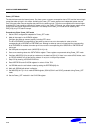
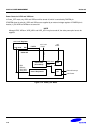
Procedure to Wake-up from Power_OFF mode
1. The internal reset signal will be asserted if one of the wake-up sources is issued. This reset duration is
determined by the internal 16-bit counter logic and the reset assertion time is calculated as tRST = (65535 /
XTAL_frequency).
2. Check GSTATUS2[2] in order to know whether or not the power-up is caused by the wake-up from Power_OFF
mode.
3. Release the SDRAM signal protection by setting MISCCR[19:17]=000b.
4. Configure the SDRAM memory controller.
5. Wait until the SDRAM self-refresh is released. Mostly SDRAM needs the refresh cycle of all SDRAM row.
6. The information in GSTATUS3,4 can be used for user's own purpose because the value in GSTATUS3,4 has
been preserved during Power_OFF mode.
7. – For EINT[3:0], check the SRCPND register.
– For EINT[15:4], check the EINTPEND instead of SRCPND (SRCPND will not be set although some bits of
EINTPEND are set.).
– For alarm wake-up, check the RTC time because the RTC bit of SRCPND isn't set at the alarm wake-up.
– If there was the nBATT_FLT assertion during POWER_OFF mode, the corresponding bit of SRCPND has
been set.
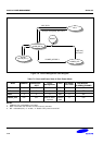
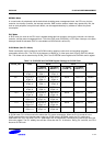
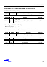
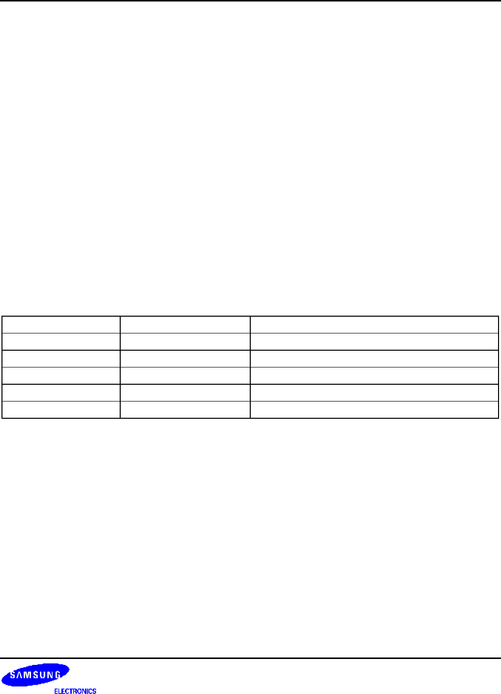
Pin States in Power_OFF Mode
The pin state of the Power_OFF mode is as follows;
Pin Type Pin Example Pin States in Power_OFF Mode
GPIO output pin GPB0: output Output ( GPIO data register value is used.)
GPIO input pin GPB0: input Input
GPIO bi-directional pin GPG6:SPIMOSI Input
Function output pin nGCS0 Output (the last output level is held.)
Function input pin nWAIT Input