


S3C2410A ARM INSTRUCTION SET
3-35
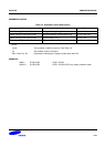
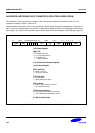
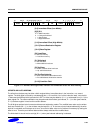
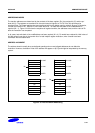
31 27 19 15
Cond
28 16 11122123
1
20
L Rn Rd
[3:0] Immediate Offset (Low Nibble)
[6][5] S H
0 0 = SWP instruction
0 1 = Unsigned halfword
1 1 = Signed byte
1 1 = Signed halfword
[11:8] Immediate Offset (High Nibble)
[15:12] Source/Destination Register
[19:16] Base Register
[20] Load/Store
0 = Store to memory
1 = Load from memory
[21] Write-back
0 = No write-back
1 = Write address into base
[23] Up/Down
0 = Down: subtract offset from base
1 = Up: add offset to base
[24] Pre/Post Indexing
0 = Post: add/subtract offset after transfer
1 = Pre: add/subtract offset bofore transfer
[31:28] Condition Field
22
000 P U OffsetW
2425
1 OffsetS H 1
8 7 6 5 4 3 0
Figure 3-17. Halfword and Signed Data Transfer with Immediate Offset and Auto-Indexing
OFFSETS AND AUTO-INDEXING
The offset from the base may be either a 8-bit unsigned binary immediate value in the instruction, or a second
register. The 8-bit offset is formed by concatenating bits 11 to 8 and bits 3 to 0 of the instruction word, such that bit
11 becomes the MSB and bit 0 becomes the LSB. The offset may be added to (U = 1) or subtracted from (U = 0) the
base register Rn. The offset modification may be performed either before (pre-indexed, P = 1) or after (post-indexed,
P = 0) the base register is used as the transfer address.
The W bit gives optional auto-increment and decrement addressing modes. The modified base value may be written
back into the base (W = 1), or the old base may be kept (W = 0). In the case of post-indexed addressing, the write
back bit is redundant and is always set to zero, since the old base value can be retained if necessary by setting the
offset to zero. Therefore post-indexed data transfers always write back the modified base.
The Write-back bit should not be set high (W = 1) when post-indexed addressing is selected.