


CLOCK & POWER MANAGEMENT S3C2410A
7-4
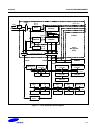
PHASE LOCKED LOOP (PLL)
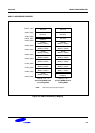
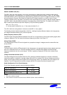
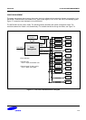
The MPLL within the clock generator, as a circuit, synchronizes an output signal with a reference input signal in
frequency and phase. In this application, it includes the following basic blocks as shown in Figure 7-2: the Voltage
Controlled Oscillator (VCO) to generate the output frequency proportional to input DC voltage, the divider P to divide
the input frequency (Fin) by p, the divider M to divide the VCO output frequency by m which is input to Phase
Frequency Detector (PFD), the divider S to divide the VCO output frequency by s which is Mpll (the output frequency
from MPLL block), the phase difference detector, the charge pump, and the loop filter. The output clock frequency
Mpll is related to the reference input clock frequency Fin by the following equation:
Mpll = (m * Fin) / (p * 2
s
)
m = M (the value for divider M)+ 8, p = P (the value for divider P) + 2
The UPLL within the clock generator is the same as the MPLL in every aspect.
The following sections describe the operation of the PLL, including the phase difference detector, the charge pump,
the Voltage controlled oscillator (VCO), and the loop filter.
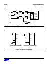
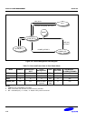
Phase Frequency Detector (PFD)
The PFD monitors the phase difference between Fref and Fvco, and generates a control signal (tracking signal) when
it detects a difference. The Fref means the reference frequency as shown in the Figure 7-2.
Charge Pump (PUMP)
The charge pump converts PFD control signals into a proportional charge in voltage across the external filter that
drives the VCO.
Loop Filter
The control signal, which the PFD generates for the charge pump, may generate large excursions (ripples) each time
the Fvco is compared to the Fref. To avoid overloading the VCO, a low pass filter samples and filters the high-
frequency components out of the control signal. The filter is typically a single-pole RC filter with a resistor and a
capacitor.
Voltage Controlled Oscillator (VCO)
The output voltage from the loop filter drives the VCO, causing its oscillation frequency to increase or decrease
linearly as a function of variations in average voltage. When the Fvco matches Fref in terms of frequency as well as
phase, the PFD stops sending control signals to the charge pump, which in turn stabilizes the input voltage to the
loop filter. The VCO frequency then remains constant, and the PLL remains fixed onto the system clock.
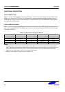
Usual Conditions for PLL & Clock Generator
PLL & Clock Generator generally uses the following conditions.
Loop filter capacitance 5 pF
External X-tal frequency
10 – 20 MHz
(note)
External capacitance used for X-tal 15 – 22 pF
NOTES:
1. The value could be changed.
2. FCLK must be more than three times X-tal or EXTCLK (FCLK ≥ 3X-tal or 3EXTCLK)