


CLOCK & POWER MANAGEMENT S3C2410A
7-6
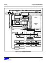
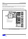
CLOCK CONTROL LOGIC
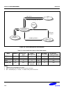
The clock control logic determines the clock source to be used, i.e., the PLL clock (Mpll) or the direct external clock
(XTIpll or EXTCLK). When PLL is configured to a new frequency value, the clock control logic disables the FCLK until
the PLL output is stabilized using the PLL locking time. The clock control logic is also activated at power-on reset
and wakeup from power-down mode.
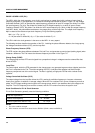
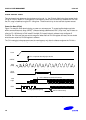
Power-On Reset (XTIpll)
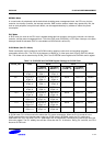
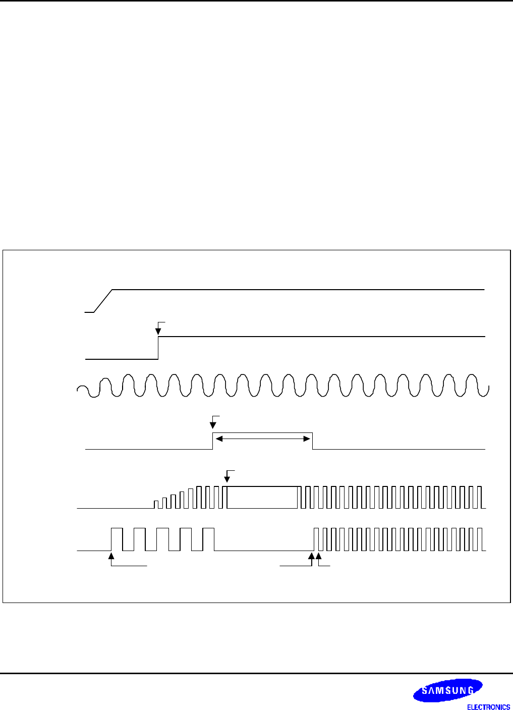
Figure 7-4 shows the clock behavior during the power-on reset sequence. The crystal oscillator begins oscillation
within several milliseconds. When nRESET is released after the stabilization of OSC (XTIpll) clock, the PLL starts to
operate according to the default PLL configuration. However, PLL is commonly known to be unstable after power-on
reset, so Fin is fed directly to FCLK instead of the Mpll (PLL output) before the software newly configures the
PLLCON. Even if the user does not want to change the default value of PLLCON register after reset, the user should
write the same value into PLLCON register by software.
The PLL restarts the lockup sequence toward the new frequency only after the software configures the PLL with a
new frequency. FCLK can be configured as PLL output (Mpll) immediately after lock time.
The logic operates by XTIpll
nRESET
OSC
(XTIpll)
VCO
output
Power
Clock
Disable
Lock Time
PLL is configured by S/W first time.
VCO is adapted to new clock frequency.
FCLK
FCLK is new frequency
PLL can operate after OM[3:2] is latched.
Figure 7-4. Power-On Reset Sequence (when the external clock source is a crystal oscillator)