


S3C2410A UART
11-3
UART OPERATION
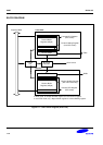
The following sections describe the UART operations that include data transmission, data reception, interrupt
generation, baud-rate generation, Loopback mode, Infra-red mode, and auto flow control.
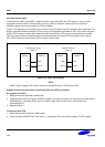
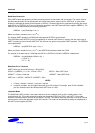
Data Transmission
The data frame for transmission is programmable. It consists of a start bit, 5 to 8 data bits, an optional parity bit and
1 to 2 stop bits, which can be specified by the line control register (ULCONn). The transmitter can also produce the
break condition, which forces the serial output to logic 0 state for one frame transmission time. This block transmits
break signals after the present transmission word is transmitted completely. After the break signal transmission, it
continuously transmits data into the Tx FIFO (Tx holding register in the case of Non-FIFO mode).
Data Reception
Like the transmission, the data frame for reception is also programmable. It consists of a start bit, 5 to 8 data bits,
an optional parity bit and 1 to 2 stop bits in the line control register (ULCONn). The receiver can detect overrun error
and frame error.
— The overrun error indicates that new data has overwritten the old data before the old data has been read.
— The frame error indicates that the received data does not have a valid stop bit.
Receive time-out condition occurs when it does not receive any data during the 3 word time (this interval follows the
setting of Word Length bit) and the Rx FIFO is not empty in the FIFO mode.