


S3C2410A USB DEVICE
13-7
INTERRUPT REGISTER (EP_INT_REG/USB_INT_REG)
The USB core has two interrupt registers.
These registers act as status registers for the MCU when it is interrupted. The bits are cleared by writing a "1" (not
"0") to each bit that was set.
Once the MCU is interrupted, MCU should read the contents of interrupt-related registers and write back to clear the
contents if it is necessary.
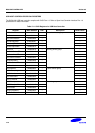
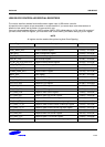
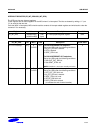
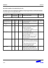
Register Address R/W Description Reset Value
EP_INT_REG 0x52000148(L)
0x5200014B(B)
R/W
(byte)
EP interrupt pending/clear register 0x00
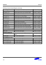
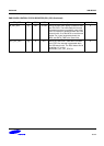
EP_INT_REG Bit MCU USB Description Initial State
EP1~EP4 Interrupt [4:1] R
/CLEAR
SET For BULK/INTERRUPT IN endpoints:
Set by the USB under the following conditions:
1. IN_PKT_RDY bit is cleared.
2. FIFO is flushed
3. SENT_STALL set.
For BULK/INTERRUPT OUT endpoints:
Set by the USB under the following conditions:
1. Sets OUT_PKT_RDY bit
2. Sets SENT_STALL bit
NOTE: Conditions 1 and 2 are mutually exclusive.
0
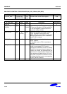
EP0 Interrupt [0] R
/CLEAR
SET Correspond to endpoint 0 interrupt.
Set by the USB under the following conditions:
1. OUT_PKT_RDY bit is set.
2. IN_PKT_RDY bit is cleared.
3. SENT_STALL bit is set
4. SETUP_END bit is set
5. DATA_END bit is cleared
(it indicates the end of control transfer).
0