


S3C2410A ARM INSTRUCTION SET
3-41
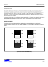
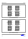
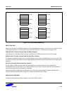
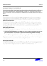
ADDRESSING MODES
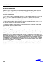
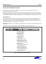
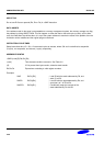
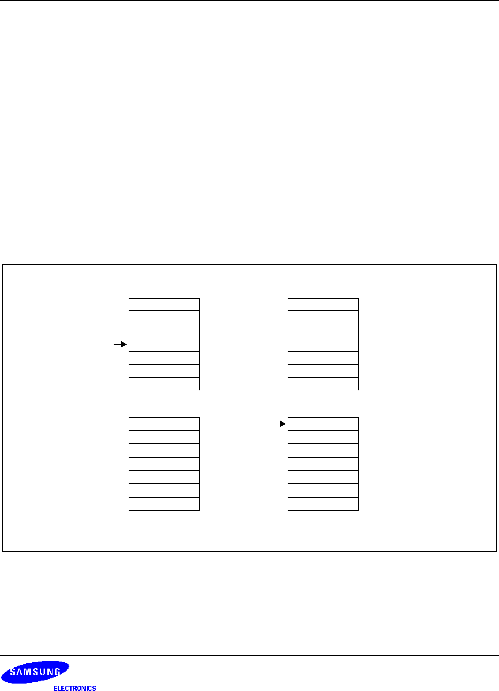
The transfer addresses are determined by the contents of the base register (Rn), the pre/post bit (P) and the up/
down bit (U). The registers are transferred in the order lowest to highest, so R15 (if in the list) will always be
transferred last. The lowest register also gets transferred to/from the lowest memory address. By way of illustration,
consider the transfer of R1, R5 and R7 in the case where Rn = 0x1000 and write back of the modified base is
required (W = 1). Figure 3.19-22 show the sequence of register transfers, the addresses used, and the value of Rn
after the instruction has completed.
In all cases, had write back of the modified base not been required (W = 0), Rn would have retained its initial value of
0x1000 unless it was also in the transfer list of a load multiple register instruction, when it would have been
overwritten with the loaded value.
ADDRESS ALIGNMENT
The address should normally be a word aligned quantity and non-word aligned addresses do not affect the
instruction. However, the bottom 2 bits of the address will appear on A[1:0] and might be interpreted by the memory
system.
1 2
3 4
Rn R1
R1
R5
R1
R5
R7
Rn
0x100C
0x1000
0x0FF4
0x100C
0x1000
0x0FF4
0x100C
0x1000
0x0FF4
0x100C
0x1000
0x0FF4
Figure 3-19. Post-Increment Addressing