


S3C2410A SPI INTERFACE
22-7
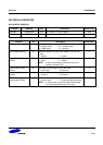
SPI SPECIAL REGISTERS
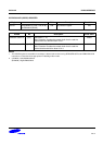
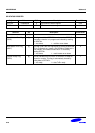
SPI CONTROL REGISTER
Register Address R/W Description Reset Value
SPCON0 0x59000000 R/W SPI channel 0 control register 0x00
SPCON1 0x59000020 R/W SPI channel 1 control register 0x00
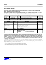
SPCONn Bit Description Initial State
SPI Mode Select (SMOD) [6:5] Determine how and by what SPTDAT is read/written.
00 = polling mode, 01 = interrupt mode
10 = DMA mode, 11 = reserved
00
SCK Enable (ENSCK) [4] Determine whether you want SCK enable or not (for only
master).
0 = disable, 1 = enable
0
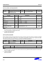
Master/Slave Select
(MSTR)
[3] Determine the desired mode (master or slave).
0 = slave, 1 = master
NOTE: In slave mode, there should be set up time for
master to initiate Tx/Rx.
0
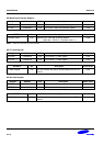
Clock Polarity Select
(CPOL)
[2] Determine an active high or active low clock.
0 = active high, 1 = active low
0
Clock Phase Select
(CPHA)
[1] Select one of two fundamentally different transfer formats.
0 = format A, 1 = format B
0
Tx Auto Garbage Data
mode enable (TAGD)
[0] Decide whether the receiving data only needs or not.
0 = normal mode, 1 = Tx auto garbage data mode
NOTE: In normal mode, if you only want to receive data,
you should transmit dummy 0xFF data.
0