


S3C2410A SPI INTERFACE
22-5
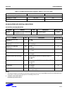
Transmitting Procedure by DMA
1. The SPI is configured as DMA mode.
2. DMA is configured properly.
3. The SPI requests DMA service.
4. DMA transmits 1byte data to the SPI.
5. The SPI transmits the data to card.
6. Return to Step 3 until DMA count becomes 0.
7. The SPI is configured as interrupt or polling mode with SMOD bits.
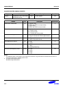
Receiving Procedure by DMA
1. The SPI is configured as DMA start with SMOD bits and setting TAGD bit.
2. DMA is configured properly.
3. The SPI receives 1byte data from card.
4. The SPI requests DMA service.
5. DMA receives the data from the SPI.
6. Write data 0xFF automatically to SPTDATn.
7. Return to Step 4 until DMA count becomes 0.
8. The SPI is configured as polling mode with SMOD bits and clearing TAGD bit.
9. If SPSTAn's REDY flag is set, then read the last byte data.
NOTE
Total received data = DMA TC values + the last data in polling mode (Step 9).
The first DMA received data is dummy and so the user can neglect it.
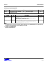
SPI Slave Rx Mode with Format B
If the SPI slave Rx mode is activated and SPI format is set to format B, then SPI operation will be failed:
The READY signal, one of internal signals, becomes high before the SPI_CNT reaches 0. Therefore, in DMA mode,
DATA_READ signal is generated before the last data is latched.