


S3C2410A UART
11-11
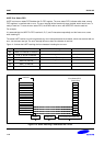
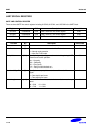
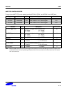
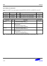
UART CONTROL REGISTER
There are three UART control registers including UCON0, UCON1 and UCON2 in the UART block.
Register Address R/W Description Reset Value
UCON0 0x50000004 R/W UART channel 0 control register 0x00
UCON1 0x50004004 R/W UART channel 1 control register 0x00
UCON2 0x50008004 R/W UART channel 2 control register 0x00
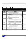
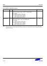
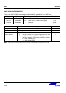
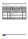
UCONn Bit Description Initial State
Clock Selection [10] Select PCLK or UEXTCLK for the UART baud rate.
0=PCLK : UBRDIVn = (int)(PCLK / (bps x 16) ) -1
1=UEXTCLK(@GPH8) : UBRDIVn = (int)(UEXTCLK / (bps x 16) ) -1
0
Tx Interrupt Type [9] Interrupt request type.
0 = Pulse (Interrupt is requested as soon as the Tx buffer becomes
empty in Non-FIFO mode or reaches Tx FIFO Trigger Level in FIFO
mode.)
1 = Level (Interrupt is requested while Tx buffer is empty in Non-FIFO
mode or reaches Tx FIFO Trigger Level in FIFO mode.)
0
Rx Interrupt Type [8] Interrupt request type.
0 = Pulse (Interrupt is requested the instant Rx buffer receives the
data in Non-FIFO mode or reaches Rx FIFO Trigger Level in FIFO
mode.)
1 = Level (Interrupt is requested while Rx buffer is receiving data in
Non-FIFO mode or reaches Rx FIFO Trigger Level in FIFO mode.)
0
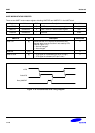
Rx Time Out
Enable
[7] Enable/Disable Rx time out interrupt when UART FIFO is enabled.
The interrupt is a receive interrupt.
0 = Disable 1 = Enable
0
Rx Error Status
Interrupt Enable
[6] Enable the UART to generate an interrupt upon an exception, such as
a frame error, or overrun error during a receive operation.
0 = Do not generate receive error status interrupt.
1 = Generate receive error status interrupt.
0
Loopback Mode [5] Setting loopback bit to 1 causes the UART to enter the loopback
mode. This mode is provided for test purposes only.
0 = Normal operation 1 = Loopback mode
0
Reserved [4] Reserved 0