


S3C2410A REAL TIME CLOCK (RTC)
17-3
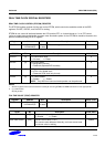
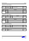
READ/WRITE REGISTERS
Bit 0 of the RTCCON register must be set high in order to write the BCD register in RTC block. To display the
second, minute, hour, date, month, and year, the CPU should read the data in BCDSEC, BCDMIN, BCDHOUR,
BCDDAY, BCDDATE, BCDMON, and BCDYEAR registers, respectively, in the RTC block. However, a one second
deviation may exist because multiple registers are read. For example, when the user reads the registers from
BCDYEAR to BCDMIN, the result is assumed to be 2059 (Year), 12 (Month), 31 (Date), 23 (Hour) and 59 (Minute).
When the user read the BCDSEC register and the value ranges from 1 to 59 (Second), there is no problem, but, if the
value is 0 sec., the year, month, date, hour, and minute may be changed to 2060 (Year), 1 (Month), 1 (Date), 0
(Hour) and 0 (Minute) because of the one second deviation that was mentioned. In this case, the user should re-read
from BCDYEAR to BCDSEC if BCDSEC is zero.
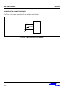
BACKUP BATTERY OPERATION
The RTC logic can be driven by the backup battery, which supplies the power through the RTCVDD pin into the RTC
block, even if the system power is off. When the system is off, the interfaces of the CPU and RTC logic should be
blocked, and the backup battery only drives the oscillation circuit and the BCD counters to minimize power
dissipation.
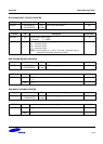
ALARM FUNCTION
The RTC generates an alarm signal at a specified time in the power-off mode or normal operation mode. In normal
operation mode, the alarm interrupt (ALMINT) is activated. In the power-off mode, the power management wakeup
(PMWKUP) signal is activated as well as the ALMINT. The RTC alarm register (RTCALM) determines the alarm
enable/disable status and the condition of the alarm time setting.
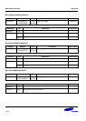
TICK TIME INTERRUPT
The RTC tick time is used for interrupt request. The TICNT register has an interrupt enable bit and the count value for
the interrupt. The count value reaches '0' when the tick time interrupt occurs. Then the period of interrupt is as
follows:
Period = ( n+1 ) / 128 second
n: Tick time count value (1~127)
This RTC time tick may be used for real time operating system (RTOS) kernel time tick. If time tick is generated by
the RTC time tick, the time related function of RTOS will always synchronized in real time.
ROUND RESET FUNCTION
The round reset function can be performed by the RTC round reset register (RTCRST). The round boundary (30, 40,
or 50 sec.) of the second carry generation can be selected, and the second value is rounded to zero in the round
reset. For example, when the current time is 23:37:47 and the round boundary is selected to 40 sec, the round reset
changes the current time to 23:38:00.
NOTE
All RTC registers have to be accessed for each byte unit using the STRB and LDRB instructions or char
type pointer.