CLOCK & POWER MANAGEMENT S3C2410A
7-10
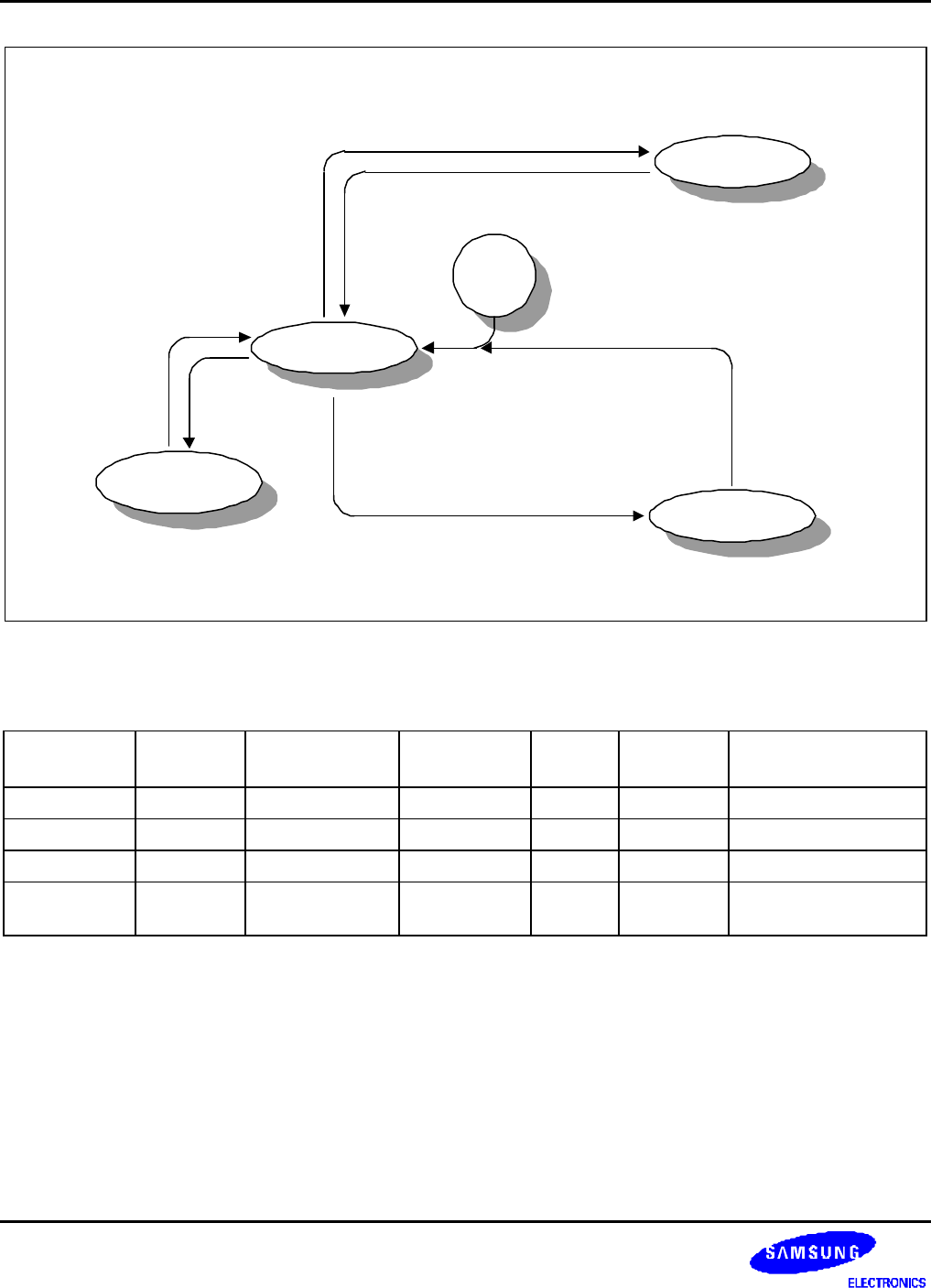
IDLE
POWER_OFF
NORMAL
(SLOW_BIT=0)
SLOW
(SLOW_BIT=1)
IDLE_BIT=1
Interrupts, EINT[0:23], RTC alarm
POWER_OFF BIT=1
EINT[15:0],
RTC alarm
RESET
Figure 7-8. Power Management State Diagram
Table 7-2. Clock and Power State in Each Power Mode
Mode ARM920T
AHB Modules
(1)
/WDT
Power
Management
GPIO 32.768kHz
RTC clock
APB Modules
(2)
& USBH/LCD/NAND
NORMAL O O O SEL O SEL
IDLE X O O SEL O SEL
SLOW O O O SEL O SEL
POWER_OFF OFF OFF Wait for wake-
up event
Previous
state
O OFF
NOTES:
1. USB host,LCD, and NAND are excluded.
2. WDT is excluded. RTC interface for CPU access is included.
3. SEL : selectable(O,X), O : enable , X : disable OFF: power is turned off


