


S3C2410A ARM INSTRUCTION SET
3-37
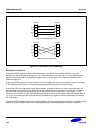
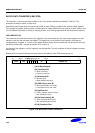
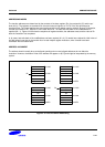
Big-Endian Configuration
A signed byte load (LDRSB) expects data on data bus inputs 31 through to 24 if the supplied address is on a word
boundary, on data bus inputs 23 through to 16 if it is a word address plus one byte, and so on. The selected byte is
placed in the bottom 8 bit of the destination register, and the remaining bits of the register are filled with the sign bit,
bit 7 of the byte. Please see Figure 2-1.
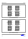
A halfword load (LDRSH or LDRH) expects data on data bus inputs 31 through to 16 if the supplied address is on a
word boundary and on data bus inputs 15 through to 0 if it is a halfword boundary, (A[1]=1). The supplied address
should always be on a halfword boundary. If bit 0 of the supplied address is HIGH then the ARM920T will load an
unpredictable value. The selected halfword is placed in the bottom 16 bits of the destination register. For unsigned
half-words (LDRH), the top 16 bits of the register are filled with zeros and for signed half-words (LDRSH) the top 16
bits are filled with the sign bit, bit 15 of the halfword.
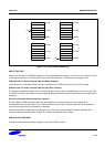
A halfword store (STRH) repeats the bottom 16 bits of the source register twice across the data bus outputs 31
through to 0. The external memory system should activate the appropriate halfword subsystem to store the data.
Note that the address must be halfword aligned, if bit 0 of the address is HIGH this will cause unpredictable
behaviour.
USE OF R15
Write-back should not be specified if R15 is specified as the base register (Rn). When using R15 as the base
register you must remember it contains an address 8 bytes on from the address of the current instruction.
R15 should not be specified as the register offset (Rm).
When R15 is the source register (Rd) of a Half-word store (STRH) instruction, the stored address will be address of
the instruction plus 12.
DATA ABORTS
A transfer to or from a legal address may cause problems for a memory management system. For instance, in a
system which uses virtual memory the required data may be absent from the main memory. The memory manager
can signal a problem by taking the processor ABORT input HIGH whereupon the Data Abort trap will be taken. It is
up to the system software to resolve the cause of the problem, then the instruction can be restarted and the original
program continued.
INSTRUCTION CYCLE TIMES
Normal LDR(H,SH,SB) instructions take 1S + 1N + 1I. LDR(H,SH,SB) PC take 2S + 2N + 1I incremental cycles.
S,N and I are defined as sequential (S-cycle), non-sequential (N-cycle), and internal (I-cycle), respectively. STRH
instructions take 2N incremental cycles to execute.