


PROGRAMMER'S MODEL S3C2410A
2-8
The Condition Code Flags
The N, Z, C and V bits are the condition code flags. These may be changed as a result of arithmetic and logical
operations, and may be tested to determine whether an instruction should be executed.
In ARM state, all instructions may be executed conditionally: see Table 3-2 for details.
In THUMB state, only the Branch instruction is capable of conditional execution: see Figure 3-46 for details.
The Control Bits
The bottom 8 bits of a PSR (incorporating I, F, T and M[4:0]) are known collectively as the control bits. These will be
changed when an exception arises. If the processor is operating in a privileged mode, they can also be manipulated
by software.
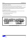
The T bit This reflects the operating state. When this bit is set, the processor is executing in THUMB
state, otherwise it is executing in ARM state. This is reflected on the TBIT external signal.
Note that the software must never change the state of the TBIT in the CPSR. If this
happens, the processor will enter an unpredictable state.
Interrupt disable
bits
The I and F bits are the interrupt disable bits. When set, these disable the IRQ and FIQ
interrupts respectively.
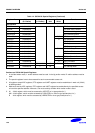
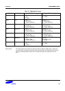
The mode bits The M4, M3, M2, M1 and M0 bits (M[4:0]) are the mode bits. These determine the
processor's operating mode, as shown in Table 2-1. Not all combinations of the mode bits
define a valid processor mode. Only those explicitly described shall be used. The user
should be aware that if any illegal value is programmed into the mode bits, M[4:0], then the
processor will enter an unrecoverable state. If this occurs, reset should be applied.
Reserved bits
The remaining bits in the PSRs are reserved. When changing a PSR's flag or control bits,
you must ensure that these unused bits are not altered. Also, your program should not rely
on them containing specific values, since in future processors they may read as one or zero.