


WATCHDOG TIMER S3C2410A
18-2
WATCHDOG TIMER OPERATION
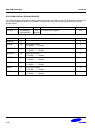
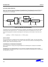
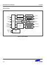
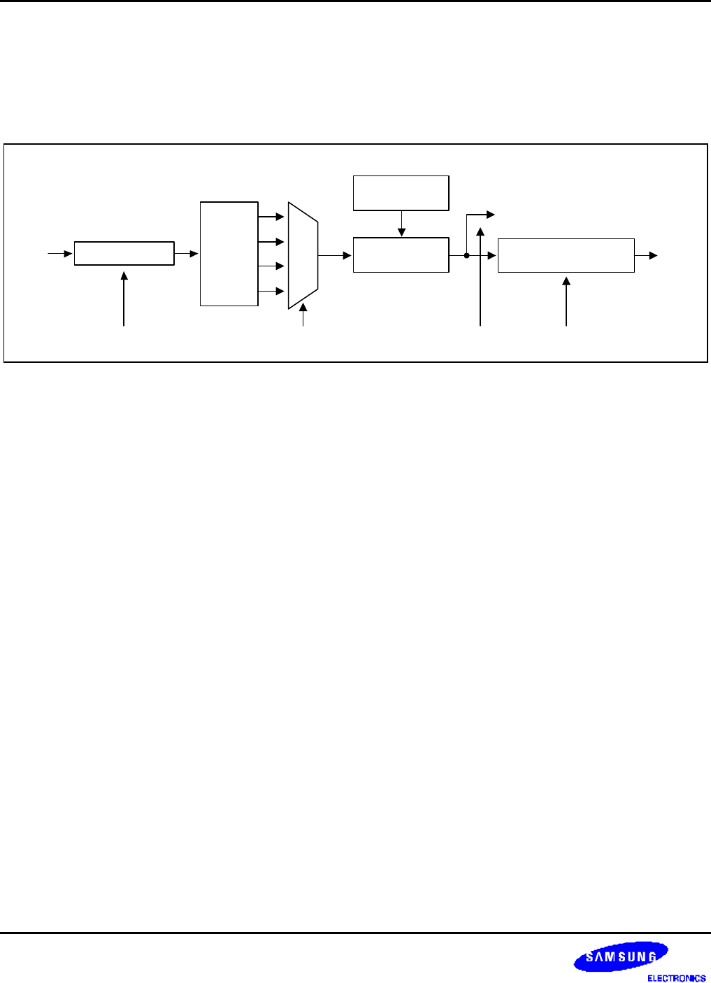
Figure 18-1 shows the functional block diagram of the watchdog timer. The watchdog timer uses only PCLK as its
source clock. The PCLK frequency is prescaled to generate the corresponding watchdog timer clock, and the
resulting frequency is divided again.
Reset Signal Generator
WTCNT
(Down Counter)
PCLK
WTCON[4:3]
WTDAT
RESET
1/16
1/32
1/64
1/128
8-bit Prescaler
WTCON[15:8] WTCON[2] WTCON[0]
Interrupt
MUX
Figure 18-1. Watchdog Timer Block Diagram
The prescaler value and the frequency division factor are specified in the watchdog timer control (WTCON) register.
Valid prescaler values range from 0 to 2
8
-1. The frequency division factor can be selected as 16, 32, 64, or 128.
Use the following equation to calculate the watchdog timer clock frequency and the duration of each timer clock
cycle:
t_watchdog = 1/( PCLK / (Prescaler value + 1) / Division_factor )
WTDAT & WTCNT
Once the watchdog timer is enabled, the value of watchdog timer data (WTDAT) register cannot be automatically
reloaded into the timer counter (WTCNT). In this reason, an initial value must be written to the watchdog timer count
(WTCNT) register, before the watchdog timer starts.
CONSIDERATION OF DEBUGGING ENVIRONMENT
When the S3C2410A is in debug mode using Embedded ICE, the watchdog timer is disabled, will be disabled
automatically.
The watchdog timer can determine whether or not it is currently in the debug mode from the CPU core signal
(DBGACK signal). Once the DBGACK signal is asserted, the reset output of the watchdog timer is not activated as
the watchdog timer is expired.