ELECTRICAL DATA S3C2410A
24-34
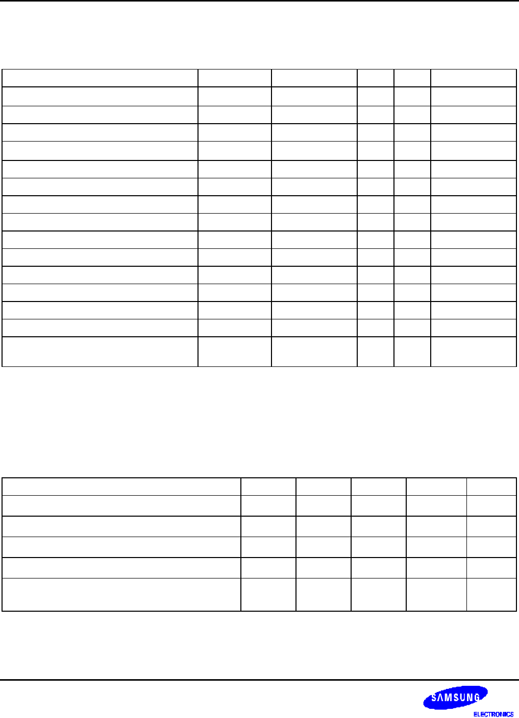
Table 24-11. TFT LCD Controller Module Signal Timing Constants
(V
DD
= 1.8V ± 0.15 / 2.0 V ± 0.1 V, T
A
= -40 to 85 °C, V
EXT
= 3.3V ± 0.3V)
Parameter Symbol Min Typ Max Units
Vertical sync pulse width Tvspw VSPW + 1 – –
Phclk
(note1)
Vertical back porch delay Tvbpd VBPD+1 – – Phclk
Vertical front porch dealy Tvfpd VFPD+1 – – Phclk
VCLK pulse width Tvclk 1 – –
Pvclk
(note2)
VCLK pulse width high Tvclkh 0.5 – – Pvclk
VCLK pulse width low Tvclkl 0.5 – – Pvclk
Hsync setup to VCLK falling edge Tl2csetup 0.5 – – Pvclk
VDEN set up to VCLK falling edge Tde2csetup 0.5 – – Pvclk
VDEN hold from VCLK falling edge Tde2chold 0.5 – – Pvclk
VD setup to VCLK falling edge Tvd2csetup 0.5 – – Pvclk
VD hold from VCLK falling edge Tvd2chold 0.5 – – Pvclk
LEND width Tlewidth – 1 – Pvclk
LEND hold from VCLK rising edge Tle2chold 3 – – ns
VSYNC setup to HSYNC falling edge Tf2hsetup HSPW + 1 – – Pvclk
VSYNC hold from HSYNC falling edge Tf2hhold HBPD + HFPD +
HOZVAL + 3
– – Pvclk
NOTES:
1. HSYNC period
2. VCLK period
Table 24-12. IIS Controller Module Signal Timing Constants
(V
DD
= 1.8V ± 0.15 / 2.0 V ± 0.1 V, T
A
= -40 to 85 °C, V
EXT
= 3.3V ± 0.3V)
Parameter Symbol Min Typ. Max Unit
IISLRCK delay time t
LRCK
0.7 – 1.4 ns
IISDO delay time t
SDO
0.8 – 1.7 ns
IISDI Input Setup time t
SDIS
6.2 – 16.3 / 15.3 ns
IISDI Input Hold time t
SDIH
0.1 – 0.1 ns
CODEC clock frequency f
CODEC
1/16 – 1 f
IIS_
BLOCK


