


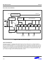
S3C2410A REAL TIME CLOCK (RTC)
17-5
REAL TIME CLOCK SPECIAL REGISTERS
REAL TIME CLOCK CONTROL (RTCCON) REGISTER
The RTCCON register consists of 4 bits such as the RTCEN, which controls the read/write enable of the BCD
registers, CLKSEL, CNTSEL, and CLKRST for testing.
RTCEN bit can control all interfaces between the CPU and the RTC, so it should be set to 1 in an RTC control
routine to enable data read/write after a system reset. Also before power off, the RTCEN bit should be cleared to 0 to
prevent inadvertent writing into RTC registers.
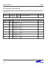
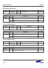
Register Address R/W Description Reset Value
RTCCON 0x57000040(L)
0x57000043(B)
R/W
(by byte)
RTC control register 0x0
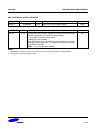
RTCCON Bit Description Initial State
CLKRST [3] RTC clock count reset.
0 = No reset, 1 = Reset
0
CNTSEL [2] BCD count select.
0 = Merge BCD counters
1 = Reserved (Separate BCD counters)
0
CLKSEL [1] BCD clock select.
0 = XTAL 1/2
15
divided clock
1 = Reserved (XTAL clock only for test)
0
RTCEN [0] RTC control enable.
0 = Disable 1 = Enable
NOTE: Only BCD time count and read operation can be performed.
0
NOTES:
1. All RTC registers have to be accessed for each byte unit using STRB and LDRB instructions or char type pointer.
2. (L): Little endian.
(B): Big endian.
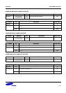
TICK TIME COUNT (TICNT) REGISTER
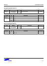
Register Address R/W Description Reset Value
TICNT 0x57000044(L)
0x57000047(B)
R/W
(by byte)
Tick time count register 0x0
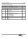
TICNT Bit Description Initial State
TICK INT ENABLE [7] Tick time interrupt enable.
0 = Disable 1 = Enable
0
TICK TIME COUNT [6:0] Tick time count value (1~127).
This counter value decreases internally, and users cannot read
this counter value in working.
000000