


S3C2410A IIC-BUS INTERFACE
20-1
20 IIC-BUS INTERFACE
OVERVIEW
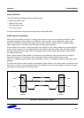
The S3C2410A RISC microprocessor can support a multi-master IIC-bus serial interface. A dedicated serial data line
(SDA) and a serial clock line (SCL) carry information between bus masters and peripheral devices which are
connected to the IIC-bus. The SDA and SCL lines are bi-directional.
In multi-master IIC-bus mode, multiple S3C2410A RISC microprocessors can receive or transmit serial data to or
from slave devices. The master S3C2410A can initiate and terminate a data transfer over the IIC-bus. The IIC-bus in
the S3C2410A uses Standard bus arbitration procedure.
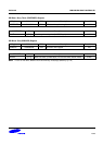
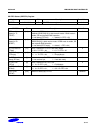
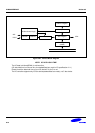
To control multi-master IIC-bus operations, values must be written to the following registers:
— Multi-master IIC-bus control register, IICCON
— Multi-master IIC-bus control/status register, IICSTAT
— Multi-master IIC-bus Tx/Rx data shift register, IICDS
— Multi-master IIC-bus address register, IICADD
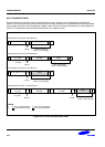
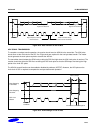
When the IIC-bus is free, the SDA and SCL lines should be both at High level. A High-to-Low transition of SDA can
initiate a Start condition. A Low-to-High transition of SDA can initiate a Stop condition while SCL remains steady at
High Level.
The Start and Stop conditions can always be generated by the master devices. A 7-bit address value in the first data
byte, which is put onto the bus after the Start condition has been initiated, can determine the slave device which the
bus master device has selected. The 8th bit determines the direction of the transfer (read or write).
Every data byte put onto the SDA line should be eight bits in total. The bytes can be unlimitedly sent or received
during the bus transfer operation. Data is always sent from most-significant bit (MSB) first, and every byte should be
immediately followed by an acknowledge (ACK) bit.