


Program mode: HD-1
128
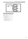
Bus Sel. (Bus Select) [L/R, 1…8, 1/2…7/8, Off]
Specifies the bus to which the signal will be sent
immediately after the insert effect.
L/R: The signal will be sent to the L/R bus, which
passes through TFX 1 and 2 and then goes to the main
L/R outputs. This is the default setting.
1…8: The signal will be sent, in mono, to the selected
individual output.
1/2…7/8: The signal will be panned by the Pan (CC#8)
setting, and sent in stereo to the selected pair of audio
outputs.
Off: The signal will not be sent directly to the outputs.
This setting is useful if you want to:
• Use Send 1 or 2 to route the signal entirely through
the master effects, without sending the dry signal to
the outputs.
• Use the FX Control Bus to route the signal to an
effects side-chain, such as a gate or vocoder,
without being heard directly at the outputs.
• Use the REC Bus to record the signal, without
routing the signal directly to the outputs.
FX Control Bus [Off, 1, 2]
This sends the post-IFX signal to the FX Control
busses. For more information, see “8–1d: FX Control
Bus” on page 124.
REC Bus [Off, 1, 2, 3, 4, 1/2, 3/4]
Sends the post-IFX signal to the REC busses. For more
information, see See “8–1e: REC Bus” on page 124. If
you want to resample via the REC busses, set the
sampling Source Bus (0–8d) to REC 1/2 or REC 3/4.
Send1 [000…127]
Send2 [000…127]
These adjust the level at which the post-IFX signal is
sent to master effects 1 and 2. This is valid if Bus Select
(8–5a) is set to L/R or Off.
Note: You can use the control surface to control Send1
and Send2. (See “8–1f: OSC MFX Send” on page 125)
You can use CC#93 to control the Send 1 level, and
CC#91 to control the Send 2 level. The global MIDI
channel specified by MIDI Channel (Global 1–1a) is
used for these messages.
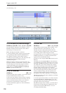
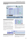
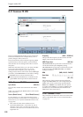
IFX2…12
Here you can specify each insert effect’s effect type,
on/off status, chaining, and mixer settings following
the insert effect. With the exception of Chain to and
Chain, the parameters are the same as for IFX1. See
“IFX1” on page 127.
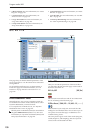
IFX2: Chain to [IFX3…IFX12]
IFX3: Chain to [IFX4…IFX12]
IFX4: Chain to [IFX5…IFX12]
IFX5: Chain to [IFX6…IFX12]
IFX6: Chain to [IFX7…IFX12]
IFX7: Chain to [IFX8…IFX12]
IFX8: Chain to [IFX9…IFX12]
IFX9: Chain to [IFX10…IFX12]
IFX10: Chain to [IFX11…IFX12]
IFX11: Chain to [(IFX12)]
These specify the chain destination for each insert
effect. If Chain is enabled, the insert effect will be
connected in series to the IFX specified by the Chain to
setting.
Chain [Off, On]
Specifies whether insert effects will be connected in
series.
If the Chain check box is on, this insert effect will be
connected in series to the insert effect selected by
“Chain to.” This is not available for IFX12.
Tip: If you move from this page to the P8– IFX1–12
page, the IFX you choose here will be selected.
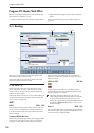
▼ 8–5: Page Menu Commands
The number before each command shows its ENTER +
number-key shortcut. For more information on these
shortcuts, see “ENTER + 0-9: shortcuts for menu
commands” on page 138.
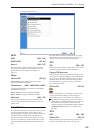
• 0: Write Program. For more information, see “Write
Program” on page 138.
• 1: Exclusive Solo. For more information, see
“Exclusive Solo” on page 138.
• 2: Copy Insert Effect. For more information, see
“Copy Insert Effect” on page 149.
• 3: Swap Insert Effects. For more information, see
“Swap Insert Effect” on page 150.
• 4: Insert IFX Slot. For more information, see “Insert
IFX Slot” on page 150.
• 5: Cut IFX Slot. For more information, see “Cut IFX
Slot” on page 151.
• 6: Clean Up IFX Routings. For more information,
see “Clean Up IFX Routings” on page 152.