


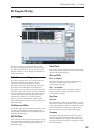

Program P5: MG, EG, & Modulation 5-1: MG, EG, & Modulation
291
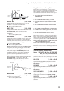
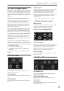
EG 2 HOLD TIME
ATTACK TIME [0.00…10.00]
Adjusts the time from the EG trigger (e.g., note-on)
until the EG reaches its maximum value.
This is scaled by MIDI CC#73.
DECAY TIME [0.00…10.00]
Adjusts the time the EG takes to descend from the peak
to the sustain level. It also controls the rate at which
SUSTAIN LEVEL, below, responds to AMS
modulation.
This is scaled by MIDI CC#75.
SUSTAIN LEVEL [0.00…10.00]
Adjusts the sustain level. The EG will stay at this level
until the trigger is released (such as when the note is
released). Unlike most other EGs, this level responds to
AMS modulation in realtime, moving at the
programmed DECAY TIME.
This is scaled by MIDI CC#70.
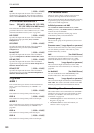
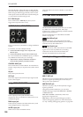
Note: with the default connection to the HPF and LPF
frequencies, this setting has a slightly unusual effect.
The SUSTAIN LEVEL always produces the same
effect as the setting of the FREQUENCY knob. The
EG2/EXT setting controls the intensity of the filter
modulation during the Attack, Decay, and Release
portions of the envelope, but does not affect the
Sustain at all.
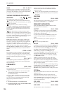
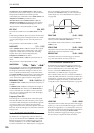
Effectively, the EG shifts up and down inversely to the
SUSTAIN LEVEL, as shown below. When the
SUSTAIN is high, the EG shifts down; when the
SUSTAIN is low, the EG shifts up.
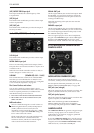
RELEASE TIME [0.00…10.00]
Adjusts the time from the trigger release (e.g., note-off)
until the level decays to zero.
This is scaled by MIDI CC#72.
Using EGs 3–6 to control the amplitude
EG 2 is always connected to the VCA. It’s possible,
however, to force the VCA to its maximum value at all
times, and then use AMS modulation of the main
VOLUME knob to control the amplitude from any of
the multi-segment EGs 3–6. To do so:
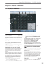
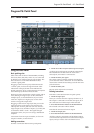
1. On the Patch Panel page, select the main
VOLUME knob.
2. Set the VOLUME knob to 0.
3. Set the VOLUME AMS Intensity to +10.00.
4. Assign the desired EG (3–6) as the knob’s AMS
source.
5. Set the VOICE ALLOCATION parameter to the
same EG.
6. Select the Mod Switch jack.
7. Set the Mod Switch AMS Source to AMS Mixer 1.
8. In AMS Mixer 1, set the Type to Gate, the Source
to Note Number, and the Threshold to -99.
9. Set both Below Threshold and At & Above
Threshold to fixed values of +33.
These settings produce a “5 volt” signal on the Patch
Panel, which, when connected to the INITIAL GAIN
input, sets the VCA to its maximum level. This lets you
control the amplitude entirely via the VOLUME AMS.
10.On the Patch Panel, connect the Mod Switch jack
to the VCA INITIAL GAIN input.
11.For the EG assigned in step 4, set up the times,
levels, and curvatures as desired.
Remember to use curvature on the EG segments, for an
analog feel!
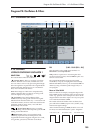
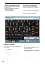
5–1e: EXTERNAL MODULATION 1
Source [Off, MG Tri, MG Pulse, EG 1, EG 1 REV,
EG 2, EG 2 REV, List of AMS Sources]
This selects the modulation source to control the
parameters below. For a list of AMS sources, see “AMS
(Alternate Modulation Source) List” on page 967.
HPF CUTOFF [–10.00…+10.00]
Specifies the depth and direction of the modulation
applied to the high-pass filter (HPF) CUTOFF
FREQUENCY.
LPF CUTOFF [–10.00…+10.00]
Specifies the depth and direction of the modulation
applied to the low-pass filter (LPF) CUTOFF
FREQUENCY
VCO1 PULSE WIDTH [–10.00…+10.00]
Specifies the depth and direction of the modulation
applied to the oscillator 1 (VCO1) PULSE WIDTH.
VCO2 PITCH [–24.00…+24.00]
Specifies the depth and direction of the modulation
applied to the oscillator 2 (VCO2) PITCH, in
semitones.
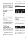
Hold Time
Trigger
On
Trigger
Off
Attack
Time
Decay
Time
Release
Time
Change to
Parameter
Value
Sustain
Level
Time
Change to
FREQUENCY
knob setting
Filter Frequency
Sustain = High
Sustain = Low
Sustain = Medium