


EXi: MS-20EX
300
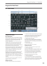
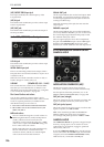
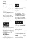
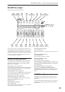
SIGNAL IN jack
This is the input to the External Signal Processor. To
use this with live audio input, connect the EXi AUDIO
IN jack to the SIGNAL IN jack.
SIGNAL LEVEL knob [0.00…10.00]
This adjusts the volume of the signal connected to the
SIGNAL IN jack.
This knob has over 50dB of gain at the maximum
setting of 10.00. Unity gain (+0dB) is at 3.75; 5.00 is
about +4dB, and 7.50 is about +12dB.
If the input level is high, setting above unity gain will
cause increasing amounts of saturation and overdrive,
creating a more aggressive tone.
(SIGNAL) OUT jack
This is the signal from the SIGNAL IN jack, scaled by
the SIGNAL LEVEL control.
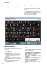
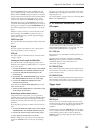
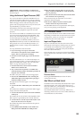
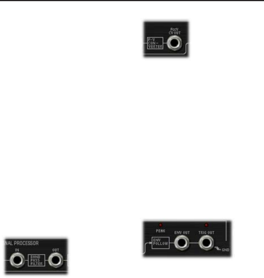
BAND PASS FILTER
The Bandpass filter includes separate controls for high
and low cut, and passes through only the audio
between those two frequencies. It’s normalled to the
input of the Frequency-to-Voltage converter, for fine-
tuning the incoming audio.
You can also use this filter to process audio signals, or
to sculpt the Noise Generator’s output for particular
modulation effects. You can even use it as a third filter
for the VCOs, in addition to the HPF and LPF.
Note: Even at the widest settings for high and low cut,
there will still be some attenuation of the highest and
lowest frequencies.
(BAND PASS FILTER) IN jack
This Patch Panel modification provides a direct input
to the Bandpass filter. This means that you can use the
filter separately from the Envelope Follower, if desired.
LOW CUT FREQ knob [0.00…10.00]
This knob adjusts the low-cut frequency of the
Bandpass filter. Only frequencies higher than this will
pass through the filter.
HIGH CUT FREQ knob [0.00…10.00]
This knob adjusts the high-cut frequency of the
Bandpass filter. Only frequencies lower than this will
pass through the filter.
(BAND PASS FILTER) OUT jack
This is the output of the Bandpass filter.
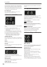
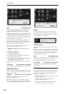
Frequency-to-Voltage (F∞V) CONVERTER
This converter generates a “control voltage” signal
based on the pitch of the audio input, which you can
then use to control the pitch of the VCOs.
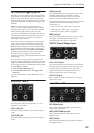
CV ADJUST knob [0.00…10.00]
Adjust this so that the input signal and the
synthesizer’s output signal are the same pitch. For
more information, see “Using the External Signal
Processor (ESP)” on page 301.
F∞V CV OUT jack
This is the output of the F-V CONVERTER. You can
connect this to the VCO 1+2 CV IN or VCO 2 CV IN
jacks, to control the oscillator pitch.
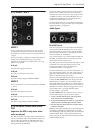
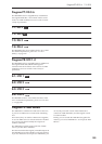
ENVELOPE FOLLOWER and TRIG OUT
The ENVELOPE FOLLOWER creates a control signal
out of the audio input level. For instance, you could
connect the ENV OUT to the LPF CUTOFF FREQ
input, to create an auto-wah filter.
The ENVELOPE FOLLOWER takes its input from the
volume-scaled SIGNAL IN, right after the SIGNAL
LEVEL knob.
Similarly, the TRIG OUT creates a trigger signal from
the input. Use the THRESHOLD knob to set the
volume level at which the trigger occurs.
PEAK LED [Off, On]
This LED shows that the ENVELOPE FOLLOWER is
at its peak value. You can use this as an aid when
adjusting the input signal’s level and/or frequency
content for optimal performance.
ENV OUT jack
This is the output of the ENVELOPE FOLLOWER.
Connect this to any modulation input.
THRESHOLD knob [0.00…10.00]
This sets the volume level at which the trigger occurs.
Adjust this to match the
TRIG OUT jack
This is the trigger generated from the audio signal. You
can connect this to the EG 1&2 TRIG IN jack, the EG1
TRIG IN jack, or the SAMPLE & HOLD CLOCK
input.
TRIG OUT LED [Off, On]
This LED shows that input signal is over the trigger
THRESHOLD, and that the trigger output is on. You
can use this as an aid when adjusting the