


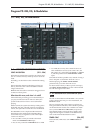
Program P6: Patch Panel 6-1: Patch Panel
297
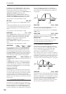
When the CLOCK input is high, the OUT jack will
carry a slightly filtered version of the signal from the
IN jack. If the CLOCK input goes high for a very brief
period of time, then the input from that instant will be
“held” at the output. The output then stays “held”
until the next time that the CLOCK input goes high.
Important: the trigger at the CLOCK input must be
very brief. When using the MG Rectangle waveform as
the trigger, for instance, turn the WAVEFORM knob to
the extreme right position; this produces a very sharp
pulse.
With this caveat in mind, you can use the MG or the
LFOs to trigger the CLOCK at regular intervals, or
trigger it manually using a switch, keyboard trigger
out, or other signal.
CLOCK input jack
This input controls the timing of the S&H, as described
above.
IN jack
This is the input to the S&H. You can connect this to
the noise generator, a VCO, an LFO, etc.
OUT jack
This is the output of the S&H, which carries the held,
“steppy” signal.
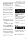
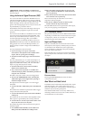
Creating the classic sample-and-hold effect
To create the classic random-stepping sample-and-
hold effect, for rhythmic, bubbling filters or “computer
noise” pitch effects:
1. Connect the WHITE or PINK output of the NOISE
GENERATOR to the SAMPLE & HOLD IN jack.
2. Connect the MG RECTANGLE output to the
CLOCK input.
3. On the MG, EG, & MODULATION page, turn the
MG WAVEFORM knob all the way to the right.
4. Connect the SAMPLE & HOLD OUT to the
modulation destination.
For instance, the LPF CUTOFF FREQ IN jack, or the
VCO 1+2 CV IN jack.
5. Adjust the MG FREQUENCY to control the speed
of the sample & hold effect.
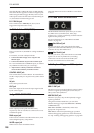
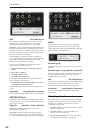
Generating a random value at note-on
Using noise as the input signal, you can generate a
random value at note-on by connecting the KBD TRIG
OUT to the CLOCK input. This will also let through
additional values at note-off, which may or may not be
desirable.
If you’d prefer to generate a random value at note-on
only:
1. Connect the WHITE or PINK output of the NOISE
GENERATOR to the SAMPLE & HOLD IN jack.
2. Connect the Switch output to the CLOCK input.
3. Leave the Switch AMS source set to Off.
With the AMS source set to Off, it will automatically
trigger the CLOCK at note-on, but not do anything
else.
Of course, you can also route a real AMS source to the
CLOCK input, and trigger it manually or via an LFO,
Step Sequencer, etc.
For a more diffuse, “splatty” effect, try connecting EG1
REV to the CLOCK input.
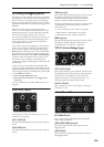
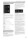
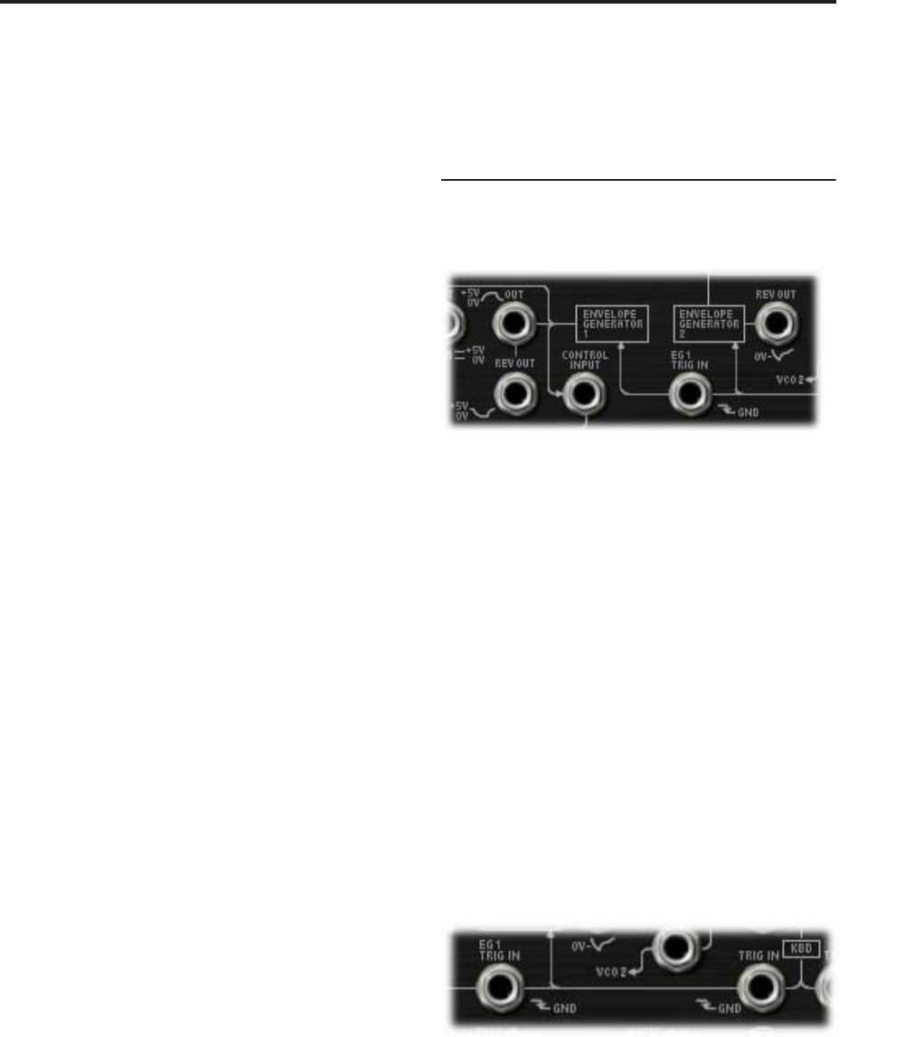
6–1e: ENVELOPE GENERATORS 1 and 2
EG outputs
For descriptions of the EG parameters, see “5–1c:
ENVELOPE GENERATOR 1” on page 290, and “5–1d:
ENVELOPE GENERATOR 2” on page 290.
EG 1 OUT jack
This allows you to route EG 1 to another point on the
Patch Panel.
Note that, when manually connected to the VCO
FREQ input, this produces a different result than the
normalled signal; for more information, see
“EG1/EXT” on page 286.
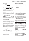
EG 1 REV OUT jack
This is the inverted shape of EG 1. The signal starts at
the maximum value, falls to 0, and then releases back
to the maximum value.
EG 2 REV OUT jack
This is the inverted shape of EG 2. The signal starts at
the maximum value, falls to 0, rises up to the sustain
level, and then releases back to the maximum value.
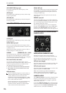
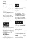
Trigger inputs
TRIG IN jack
This lets you use an external trigger sources (such as
the MG rectangle output, the trigger output of the ESP,
or a switch controller via AMS) to trigger both EG 1
and EG 2.
The EGs trigger when the TRIG IN moves from high
to low, such as when the MG Rectangle wave switches
to the bottom portion of the waveform. When the
TRIG IN signal goes high again, the EGs enter their
release phase.