


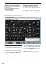
EXi: MS-20EX
290
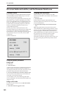
On (LED lit): When TEMPO SYNC is On, the MG
synchronizes to the system tempo, as set by either the
Tempo knob or MIDI Clock. The MG speed is
controlled by the combination of the BASE NOTE and
FREQUENCY/TIMES parameters, below.
Off (LED dark): When TEMPO SYNC is Off, the
FREQUENCY/TIMES knob determines the speed of
the MG, and the BASE NOTE setting has no effect.
This parameter is not modulatable via AMS.
KEY SYNC [ON, OFF]
Touch the text/LED area to turn KEY SYNC on and
off.
If this setting is ON, the phase is reset for the first note-
on in each legato phrase. Subsequent notes in a chord,
or notes played legato, do not cause the phase to be
reset.
This parameter is not modulatable via AMS.
BASE NOTE [1/1…1/32]
When TEMPO SYNC is ON, this sets the basic speed
of the MG, relative to the system tempo. The values
range from a 32nd note to a whole note, including
triplets. This value is then multiplied by the
FREQUENCY/TIMES knob, below.
When TEMPO SYNC is OFF, this parameter has no
effect.
This parameter is not modulatable via AMS.
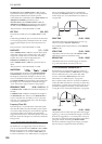
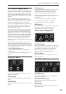
WAVE FORM [ … … ]
This controls the waveform of the MODULATION
GENERATOR. The MG always generates both the
Rectangle and Sawtooth/Triangle waveforms, and
each is available simultaneously via the Patch Panel.
The WAVE FORM knob controls the pulse width of the
Rectangle wave, and makes the Sawtooth/Triangle
“lean” from left to right, as shown in the graphics.
FREQUENCY/TIMES [0.00...10.00/16...1]
If TEMPO SYNC is OFF, this controls the frequency of
the MG.
If TEMPO SYNC is ON, this multiplies the length of
the BASE NOTE. For instance, if the BASE NOTE is
set to a sixteenth note, and Times is set to 3, the MG
will cycle over a dotted eighth note. Note that higher
values mean a faster MG.
Frequency/Times LED
This LED gives a visual indication of the LFO speed.
Note that the LED is on when the MG’s pulse/square
waveform is low. Initially, this seems like the opposite
of what one might expect. When using the MG to
trigger the EGs, however, this makes perfect sense: the
EGs start when the LED goes on, and release when the
LED goes off.
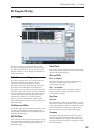
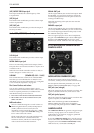
5–1c: ENVELOPE GENERATOR 1
By default, EG 1 is triggered by note-ons. However,
you can use the Patch Panel’s TRIG IN or EG 1 TRIG
IN jacks to trigger it from a different source, such as
the MG, AMS sources, or the ESP’s TRIG OUT jack.
For more information, see “TRIG IN jack” on page 297.
EG1 is normalled to VCO frequency modulation
(scaled by the EG1/EXT knob), as well as the MVCA
control input (see “6–1f: Modulation VCA (MVCA)”
on page 298).
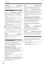
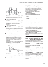
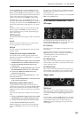
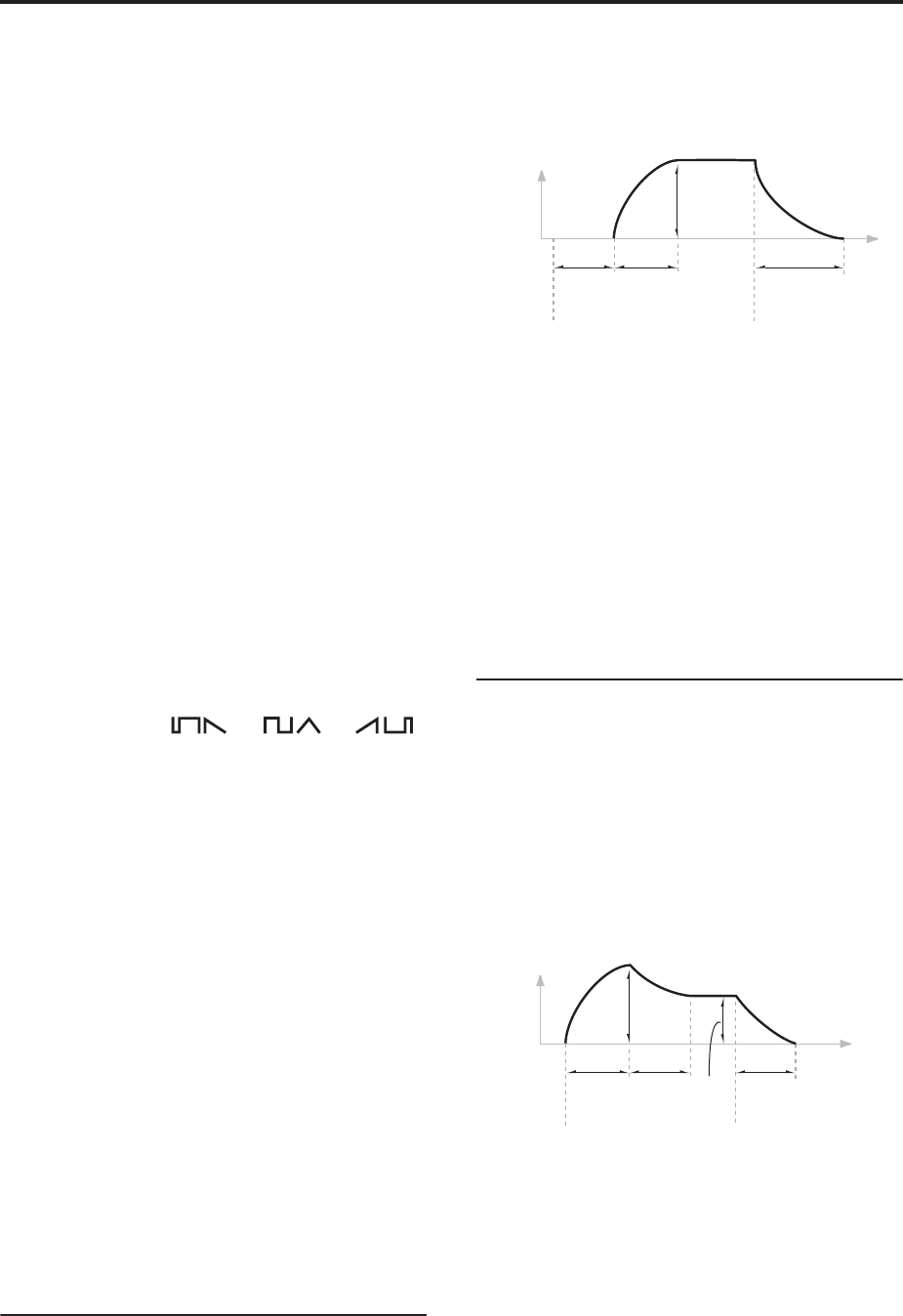
DELAY TIME [0.00…10.00]
Adjusts the time from when the trigger occurs (e.g.,
note-on) until the ATTACK TIME starts.
For standard attack-release behavior, set the DELAY
TIME to 0.00.
ATTACK TIME [0.00…10.00]
Adjusts the time from the end of the DELAY TIME
until the EG reaches its maximum value.
RELEASE TIME [0.00…10.00]
Adjusts the time from when the trigger is released
(e.g., note-off) until the level decays to zero.
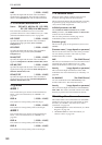
5–1d: ENVELOPE GENERATOR 2
By default, EG 2 is triggered by note-ons. However,
you can use the Patch Panel’s TRIG IN jack to trigger
it from a different source, such as the MG, AMS
sources, or the ESP’s TRIG OUT jack. For more
information, see “TRIG IN jack” on page 297.
EG 2 is hard-wired to the VCA, and also normalled to
control the HPF and LPF. You can easily use other EGs
for the filters, via AMS; using other EGs for the VCA is
possible but slightly more tricky, as described under
“Using EGs 3–6 to control the amplitude” on page 291.
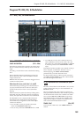
HOLD TIME [0.00…10.00]
Adjusts the time for which the input state of the trigger
signal (e.g., note-on) is held after the trigger is released.
If the EG is triggered by a very short pulse, it may not
have time to complete its attack and decay times before
going into release. Increasing the HOLD TIME
effectively makes the trigger pulse longer, giving the
EG more time to complete its attack and decay.
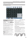
Trigger On
Trigger Off
Attack
Time
Delay
Time
Release
Time
Change to
Parameter
Value
Time
Trigger On
Trigger Off
Attack
Time
Decay
Time
Release
Time
Change to
Parameter
Value
Sustain
Level
Time