


Program P5: Filter 5–3: Filter Modulation
189
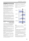
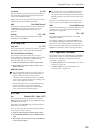
5–3a: Keyboard Track
Most acoustic instruments get brighter as you play
higher pitches. At its most basic, keyboard tracking re-
creates this effect by increasing the cutoff frequency of
a lowpass filter as you play higher on the keyboard.
Usually, some amount of key tracking is necessary in
order to make the timbre consistent across the entire
range.
The OASYS keyboard tracking can also be much more
complex, since it allows you to create different rates of
change over up to four different parts of the keyboard.
The AL-1’s Filter keyboard tracking parameters are
identical to the HD-1’s. For more detailed explanations
of the parameters, please see “3–2a: Keyboard Track,”
on page 63.
There is one difference between the two, however: the
AL-1’s Filter tracking is affected by Portamento, so that
it changes smoothly during glides.
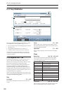
Intensity to A [–99…+99]
This controls how much the keyboard tracking will
affect Filter A ‘s cutoff frequency. The overall effect of
the Keyboard Track is a combination of this Intensity
value and the overall Keyboard Track shape.
Intensity to B [–99…+99]
This controls how much the keyboard tracking will
affect Filter B ‘s cutoff frequency.
Intensity to B applies only when the Filter Routing is
set to Serial or Parallel, and when Link is Off. In
Single and 24dB/oct modes, or if Link is On, this
parameter is grayed out.
Key
Low Break [C–1…G9]
This sets the breakpoint note between the two lower
ramps.
Center [C–1…G9]
This sets the center of the keyboard tracking. At this
key, the keyboard tracking has no effect on the filter
frequency, or on any AMS destinations.
High Break [C–1…G9]
This sets the breakpoint note between the two higher
ramps.
Ramp
The effect on the filter cutoff is a combination of the
ramp values, as set below, and the Intensity to A and B
parameters. When Intensity is set to +99, a ramp of 50
changes the filter frequency by 1 octave for every
octave of the keyboard, and a ramp of +99 changes the
frequency by 2 octaves for every octave of the
keyboard.
+Inf and –Inf are special settings which create abrupt
changes for split-like effects. When a ramp is set to +Inf
or –Inf, the keyboard tracking will go to its extreme
highest or lowest value over the span of a single key.
For more detailed explanations, please see “3–2a:
Keyboard Track,” on page 63
Bottom-Low [-Inf, –99…+99, +Inf]
This sets the slope between the bottom of the MIDI
note range and the Low Break key. For normal key
track, use negative values.
Low-Center [-Inf, –99…+99, +Inf]
This sets the slope between the Low Break and Center
keys. For normal key track, use negative values.
Center-High [-Inf, –99…+99, +Inf]
This sets the slope between the Center and High Break
keys. For normal key track, use positive values.
High-Top [-Inf, –99…+99, +Inf]
This sets the slope between the High Break key and the
top of the MIDI note range. For normal key track, use
positive values.
Key Follow
To create the classic Key Follow effect, in which the
filter frequency tracks the pitch of the keyboard:
1. Set the Filter Frequency to 30.
2. Set the Keyboard Track Intensity to +99.
3. Set the Bottom-Low and Low-Center ramps to -50.
4. Set the Center-High and High-Top ramps to +50.
5. Set the Center Key to C4.
The settings for the Low Break and High Break keys
don’t matter in this case.
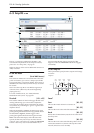
5–3b: Filter EG
The EGs modulate the Filter A and B cutoff frequencies
over time. You can control how strongly they will affect
the filters in three different ways:
• Set an initial amount of EG modulation, using the
EG Intensity parameters.
• Use velocity to scale the amount of the EG applied
to the filter.
• Use any AMS source to scale the amount of the EG
applied to the filter.
You can use all three of these at once, and the results
are added together to produce the total EG effect.
To set up the EGs themselves, including attack and
release times, levels, and so on, see “7–1: EG 1 (Filter),”
on page 199.
Filter A
EG Select [Filter EG 1, Pitch EG 2,
EG 3, EG 4, Amp EG]
This selects an EG to modulate Filter A’s Frequency.
There are four assignable EGs, in addition to the Amp
EG. Each of these can be used as a modulation source
to control a wide variety of parameters.
In the midst of all this flexibility, we thought it would
also be good to provide a little structure. With this in
mind, EG 1 is named EG 1 (Filter) and EG 2 is labeled
EG 2 (Pitch).