


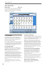
Program P0: Play 0–9: Control Surface
25
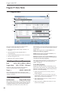
Control [SW1…8, SL1…8]
This shows which Switch or Slider is currently
selected.
Assignment [Name]
Each KARMA Slider or Switch can control multiple
internal parameters simultaneously. The group of
parameters can be given a single name, which is
shown here.
You can select different names, if desired. For more
information, see “7–9: Name/Note Map” on page 121
Module and Parameter [A 01…32, P 01…08]
This read-only display shows the KARMA
parameter(s) assigned to the Slider or Switch.
A means that the slider or switch controls a GE Real-
Time Parameter from KARMA Module A. (Note that in
Program mode, only module A is available.) The
following number identifies the specific parameter
within the module. For instance, A22å is parameter 22
of Module A.
P means that the switch is controlling a Performance
Real-Time Parameter.
You can assign many parameters to a single slider or
switch, if desired. Due to space limitations, however,
only first four parameters will be shown here. If there
are more assignments than can be displayed, you’ll see
a “>” symbol after the fourth parameter.
To change the parameter assignments, use the KARMA
GE RTP and Perf RTP pages. For more information,
please see “7–5: GE Real-Time Parameters” on
page 110, and “7–6: Perf Real-Time Parameters” on
page 112.
Parameter Value [Depends on parameter]
This shows the value of the GE or Performance Real-
Time Parameters assigned to the selected Slider or
Switch. The range can vary, depending on the
individual parameters.
Knobs 1–8
Knobs 1–4 all have dedicated functions which
correspond to MIDI CCs. Knobs 5–8 can be assigned to
a wide variety of functions, many of which also have
corresponding MIDI CCs.
When you move a knob, it sends out the
corresponding MIDI CC. Also, when the CC is
received via MIDI or generated by KARMA, the knob
value changes to match the CC value.
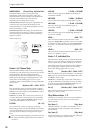
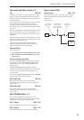
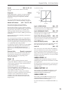
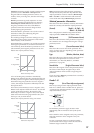
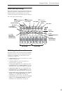
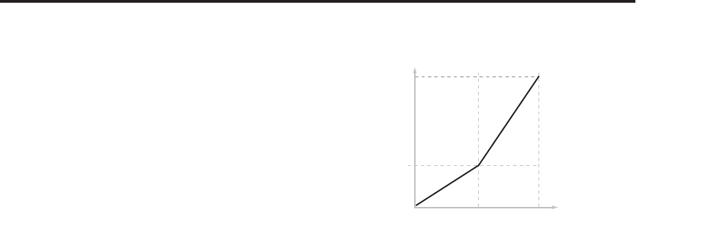
Unless otherwise noted, “scaling” means that the
parameters are at their programmed values when the
controller is at 64, at their minimum when the
controller is at 0, and at their maximum when the
controller is at 127. For another look at this, see the
diagram below.
CC parameter scaling
Knob 1: CUTOFF (CC#74) [000…127]
This knob scales the cutoff frequencies of Filters A and
B, and transmits and receives MIDI CC #74.
Knob 2: RESONANCE (CC#71) [000…127]
This knob scales the resonance of Filters A and B, and
transmits and receives MIDI CC #71.
Knob 3: Filter EG Intensity (CC#79) [000…127]
This knob scales the effect of the Filter EG on the cutoff
frequencies of Filters A and B. It also transmits and
receives MIDI CC#79.
Knob 4: EG Release (CC#72) [000…127]
This knob scales the release time of the Filter and Amp
EGs, and transmits and receives MIDI CC#72.
Knob 5–8 [000…127]
This is the current value of the knob and its MIDI CC.
You can set knobs 5–8 to a wide variety of modulation
functions, using the Controller Setup page (P1–8).
Many of the functions scale a particular set of Program
parameters. All of the settings also correspond to MIDI
messages–usually CCs.
KARMA SCENES 1–8
A KARMA Scene includes the settings for all of the
KARMA Sliders and Switches. Each Combi can contain
up to eight Scenes.
To select a Scene, just press its switch - you’ll see all of
the KARMA Sliders and Switches update instantly to
their new values.
KARMA SWITCHES 1–8
These switches control KARMA Performance or GE
(Generated Effect) parameters, as assigned on the
KARMA Perf RTP and GE RTP pages.
KARMA SLIDERS 1–8
These sliders control KARMA Performance or GE
(Generated Effect) parameters, as assigned on the
KARMA Perf RTP and GE RTP pages.
For more information, see “KARMA SWITCHES 1–8,”
above.
99
00
CC Value
Parameter
Value
As Programmed
640 127