


Global mode
644
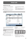
System Clock [Internal, Word Clock, S/P DIF]
This sets the system clock, or word clock, of the
OASYS.
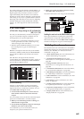
When connecting multiple digital audio devices–such
as the OASYS, an ADAT-compatible system, and a
S/P DIF device–it is important that the word clocks of
the devices be locked together. If the clocks are not
locked, the audio may be marred by pops and clicks.
The OASYS can lock to incoming clocks from any of its
digital inputs, or it can generate its own clock.
Internal: The OASYS will use its own internal clock.
This is the default setting.
Word Clock: The OASYS will use the optional EXB-
DI’s BNC WORD CLOCK IN as the master clock. The
incoming clock must be at 48kHz.
Note that this is valid only when the optional EXB-DI
is installed. For more details on the EXB-DI, please see
“EXB-DI option” on page 1041.
S/P DIF: The OASYS will use the S/P DIF IN as the
master clock. Either 48 kHz or 96 kHz word clocks are
supported, according to the S/P DIF Sample Rate
setting.
If System Clock is set to S/P DIF or Word Clock,
but the OASYS is not detecting a valid clock signal,
you’ll see the message “Clock Error!” at the top of
the display. More importantly, the OASYS will not
sound correctly.
If this occurs, check the following:
• Make sure that the word clock settings of all
connected devices are set up correctly, and that
there is one and only one device configured to be
the word clock master.
• Make sure that the device providing the master
clock is powered on.
• Make sure that all cables are undamaged, and are
connected properly. If possible, try using different
cables.
Note: The System Clock setting can be stored by the
Write Global Setting page menu command.
Power On Mode [Reset, Memorize]
Specifies the condition at power-on.
Reset: The OASYS will be in Combination mode P0:
Play, and Combination INT–A000 will be selected.
Memorize: The location (mode and page) where you
were when the power was last turned off, and the last-
selected program or combination number will be
selected.
This function does not memorize the contents of
any parameters that were edited. Before turning off
the power, be sure to write your data or save it in
Disk mode.
Internal Headroom [Standard, +12dB, +24dB,
+36dB, +48dB]
OASYS uses 32-bit floating point processing, resulting
in an outstanding internal dynamic range of about
1,500dB. This means that internal signals can get both
very loud and very soft without any noticeable
decrease in audio quality. For instance, you don’t need
to worry about turning down the oscillator level before
entering a highly resonant filter, or be too concerned
about maximizing every gain stage.
Audio input and output, on the other hand, uses
industry-standard 24-bit fixed-point A/D and D/A
converters. As with all such converters, these have a
theoretical maximum dynamic range of 144dB, and the
loudest level they can produce is referred to as 0dBfs. If
they try to produce a louder signal, they will clip at
0dBfs (and sound bad!).
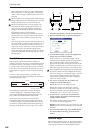
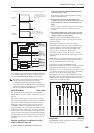
The Internal Headroom parameter helps to control the
way in which the internal 1,500dB dynamic range
interacts with the audio I/O’s theoretical 144dB
dynamic range.
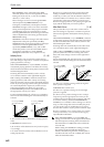
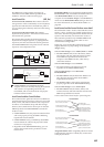
To prevent internal signal levels from becoming so
high that they completely saturate the D/A converters,
the system intentionally limits the maximum signal
level at the inputs to IFX1–12, MFX1/2, and TFX1/2.
Internal Headroom sets the volume level at which this
limiting happens, relative to the D/A’s maximum level
of 0dBfs.
When this is set to Standard, signals in the FX Busses
are limited to the clip point of the D/As. To avoid
internal clipping, you can turn down the output of the
voice (using EQ Input Trim, for instance), or turn down
the inputs or outputs of individual effects.
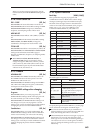
When Internal Headroom is set to +12dB, +24dB,
+36dB, or +48dB, the FX Bus signals are allowed to be
higher than the maximum D/A levels. This means that
there is less chance of clipping internally, so that you
don’t need to be as concerned about gain-staging
between individual effects. However, you still need to
make sure that the signal level is 0dBfs or below before
reaching the final outputs.
S/P DIF Sample Rate [48kHz, 96kHz(Normal),
96kHz(Hi Enhanced)]
Specifies the sample rate (sampling frequency) of the
S/P DIF input and output.
48 kHz: Digital audio will be input/output at 48 kHz.
All digital signals within the OASYS are processed at a
sampling frequency of 48 kHz.
The internal digital signals will be transmitted to and
received from external digital audio devices without
any change in the sampling rate.
96 kHz (Normal): Digital audio will be input/output
at 96 kHz. The 48 kHz internal digital signals will be
converted into 96 kHz for output. Digital signals from
a 96 kHz external digital audio device will be
converted into 48 kHz for input.
96 kHz (Hi Enhanced): Digital audio will be
input/output at 96 kHz just as for the 96 kHz (Normal)
setting. However, 96 kHz (Hi Enhanced) uses a special
algorithm only on the transmitted data, to dynamically
emphasize the high-frequency data above
approximately 20 kHz for output.