


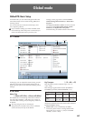
Global P0: Basic Setup 0–1: Basic
645
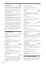
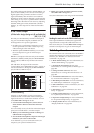
Note: ADAT OUT (if the EXB-DI is installed) channels
1–8 correspond to Indiv.1–8. If you want to output via
L/R, use the L/R Bus Indiv. Assign (0–2b) setting.
This setting will also affect tonal character of the
analog audio from the main stereo outputs
(L/MONO and R) and the headphone output.
If the signal at the S/P DIF input does not match the
selected sample rate, the upper part of the LCD will
indicate “S/P DIF CLOCK ERROR !.”
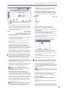
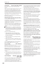
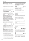
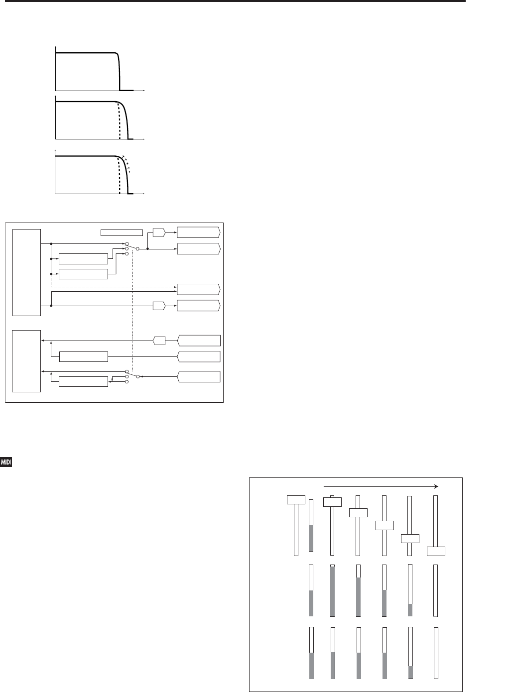
Knob/Slider Mode [Jump, Catch]
This specifies how the front panel (control surface)
MIXER sliders 1–8, master slider, and knobs 1–8 will
operate.
When you switch programs, combinations, or songs,
the written values or default values will be recalled to
the OASYS’s sliders and knobs, and the LEDs will
show those values. In the same way, when you use
CONTROL ASSIGN to switch the function of the
sliders and knobs, the value of these functions will be
recalled and shown. At this time, the actual slider and
knob locations may not necessary match the recalled
values (shown by the LEDs). The “Knob/Slider Mode”
setting specifies the point at which the value will begin
changing when you move a slider or knob in such a
situation.
Example: Switching to a combination in which
timbre 01 Volume is set to 64
1. Select a different combination, and press the
CONTROL ASSIGN MIXER TIMBRE/TRACK
switch to make 1–8 light.
Raise slider 1 to the maximum position, setting
timbre 01 Volume to 127.
2. Switch to the combination described in the
example. In the newly recalled combination, the
timbre 01 Volume value is 64 (indicated by the
LED).
Slider 1 is at the maximum position (127), meaning
that the actual value does not match the slider
position.
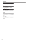
3. The “Knob/Slider Mode” setting Jump or Catch
specifies the point at which the value will begin
changing when you move slider 1.
Jump: The value will immediately change to the
controller location as soon as you move the control
surface controller.
In the above example, the value will respond
immediately when you move slider 1 slightly below
127 (for example, to 125). The disadvantage of this
setting is that the value will jump abruptly to the
current value, meaning that control will be
discontinuous. However the advantage is that the
value will respond immediately when you move the
controller.
Catch: The value will begin changing only when you
have moved the controller surface controller to the
position that matches the current value.
In the above example, the Volume will not
immediately change from the current value of 64 when
you begin lowering slider 1. As you lower slider 1
through 127 → 64 → 0, the value will change 64 → 64
→ 0. In other words, the value will begin responding
only after you Catch it. This setting can be
advantageous when you want to adjust the volume
smoothly without causing abrupt jumps. However the
disadvantage is that the controller will not respond
until you have caught the value.
Beep Enable [Off, On]
On (checked): A beep will be heard when you press an
object in the LCD screen.
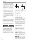
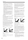
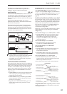
Gain
Frequency
24kHz
S/P DIF Sample Rate
= 48kHz
Gain
Frequency
24kHz
S/P DIF Sample Rate
= 96kHz (Normal)
48kHz
S/P DIF Sample Rate
= 96kHz (Hi Enhanced)
Gain
Frequency
24kHz
48kHz
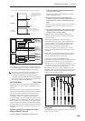
Conceptual frequency response of the audio data transmitted with each setting
These diagrams indicate the
conceptual frequency response, and
do not accurately portray the actual
frequency response.
Emphasis of the high-frequency
component is controlled dynamically
according to the output audio signal.
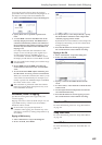
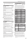
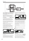
S/P DIF Sample Rate
96kHz
(Normal)
96kHz
(Hi Enhanced)
48kHz
Fs = 48kHz
Fs = 48kHz
(Digital to Analog Converter)
(Digital to Analog Converter)
(Analog to Digital Converter)
96kHz (Normal)
48kHz
96kHz (Hi Enhanced)
Fs = 48kHz or 96kHz
Fs = 48kHz or 96kHz
Fs = 48kHz
Fs = 48kHz
ADC
S/P DIF OUT (L, R)
48kHz to 96kHz
(Normal)
Conversion
48kHz to 96kHz
(Hi
Enhanced) Conversion
AUDIO OUTPUT
(L/MONO, R)
DAC
AUDIO OUTPUT
(INDIV.1, 2, 3, 4, 5, 6, 7, 8)
DAC
ADAT OUT
(1 - 8) [EXB-DI]
L/R
Indiv.1, 2, 3, 4
AUDIO INPUT
(1, 2, 3, 4)
Audio CD (L, R)
[CDRW-1]
S/P DIF IN
(L, R)
96kHz to 48kHz
Conversion
Input (Analog)
Input (S/P DIF)
Output
Input
5, 6, 7, 8
44.1kHz to 48kHz
Conversion
127
064
000
096
032
127
064
000
096
032
Operate
Setting
"Jump"
127
064
000
096
032
"Catch"
When selected