


Sampling P0: Recording 0–8: Audio Input
575
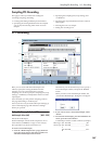
Tip: You can use the control surface to control this
parameter. (See “Using the control surface to adjust
Audio Input” on page 11.)
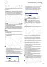
ADC OVERLOAD !
If the signal level from AUDIO INPUT 1–4 jacks is too
high, the “ADC OVERLOAD !” indication will appear.
You’ll need to adjust the MIC/LINE gain select switch,
the LEVEL knob (AUDIO INPUT 1 and 2 only), or the
output level of your external audio source.
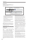
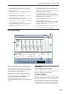
0–8b: Recording Level [dB]
Recording Level [–Inf, –72.0…+18.0]
Level Meter
CLIP !
For more information, please see “0–1c: Recording
Level [dB]” on page 570.
0–8c: Sampling Setup
Source Bus [L/R, REC1/2, REC3/4,
Audio Input1/2, Audio Input3/4, S/P DIF L/R,
Indiv.1/2, Indiv.3/4, Indiv.5/6, Indiv.7/8]
Here you can select the source that will be sampled.
The signals of the buses you select here will be
sampled.
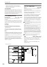
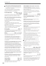
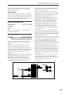
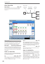
L/R: The L/R bus following TFX1 and 2 will be
sampled. The audio signals sent to the L/R bus
(specified in 1–2a) and sounds played on the OASYS
from the keyboard or via MIDI IN and sent to the L/R
bus will be sampled. Normally you will use the L/R
setting. See the diagram “Source Bus = L/R” on
page 575.
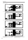
REC1/2, REC3/4: The REC1/2 or REC3/4 buses will be
sampled. Use the REC buses when you want to play
the keyboard or play back an audio CD while
sampling only the audio input. You can also mix
several audio input sources to the REC buses, or mix
the direct sound of an audio input with sound
processed by an insert effect and mix them to the REC
buses for sampling. See the diagram “Source Bus =
REC Bus 1/2” on page 576.
If you choose REC1/2, REC bus 1 is input to the L
channel and REC bus 2 is input to the R channel. If you
choose REC3/4, REC bus 3 is input to the L channel
and REC bus 4 is input to the R channel.
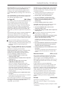
Audio Input 1/2, Audio Input 3/4: Choose these
settings if you want to directly sample the input from
AUDIO INPUT 1–4 jacks. The input from AUDIO
INPUT 1–4 jacks will be sampled directly without
being routed through the L/R bus, REC buses, or
Individual buses. AUDIO INPUT 1/2 or 3/4 will be
connected directly, regardless of the “0–8a: Audio
Input” settings for “Bus (IFX/Indiv),” Pan, and
“Level.” See the diagram “Source Bus = Audio Input
1/2” on page 576.
If you choose Audio Input 1/2, AUDIO INPUT 1 is
input to the L channel and AUDIO INPUT 2 is input to
the R channel. If you choose Audio Input 3/4, AUDIO
INPUT 3 is input to the L channel and AUDIO INPUT
4 is input to the R channel.
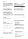
S/P DIF L/R: Choose this setting if you want to sample
the input from the S/P DIF connector. The input from
the S/P DIF jack will be sampled directly without
being routed through the L/R bus, REC buses, or
Individual buses. S/P DIF L and R will be connected
directly, regardless of the “1–2a: Audio Input” settings
for “Bus (IFX/Indiv),” Pan, and “Level.” See the
diagram “Source Bus = S/P DIF L/R” on page 576.
Indiv.1/2, Indiv.3/4, Indiv.5/6, Indiv.7/8: The Indiv.1/2–
Indiv.7/8 buses will be sampled. Choose these settings
if you want to sample only the audio inputs while
monitoring the L/R outputs, similarly to when using
the REC buses. See the diagram “Source Bus = Indiv.
1/2” on page 576.
If you choose Indiv.1/2, Indiv. bus 1 is input to the L
channel and Indiv. bus 2 is input to the R channel.
Similarly for Indiv.3/4, 5/6, or 7/8, the buses are input
to the L and R channels respectively.
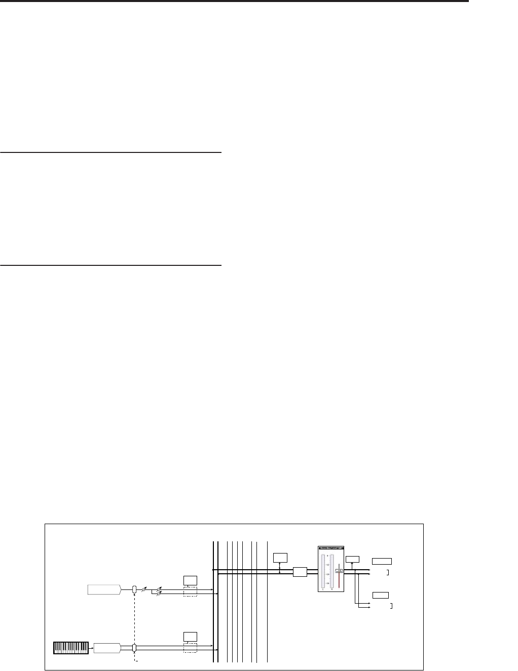
Source Bus = L/R
L-Mono
R-Mono
Stereo
Level Pan
Insert
Effects
CLIP !!
L/MONO
Source Bus = L/R
R
AUDIO OUTPUT
HEADPHONES
Insert
Effects
L/R
Bus
REC
1/2
REC
3/4
...
Indiv.
1/2
3/4 5/6 7/8
Bus = L/R or IFX1-12
CD-R/RW Drive
Audio Input
OSC
Total
Effects
Master
Effects
Sampling
Monitor