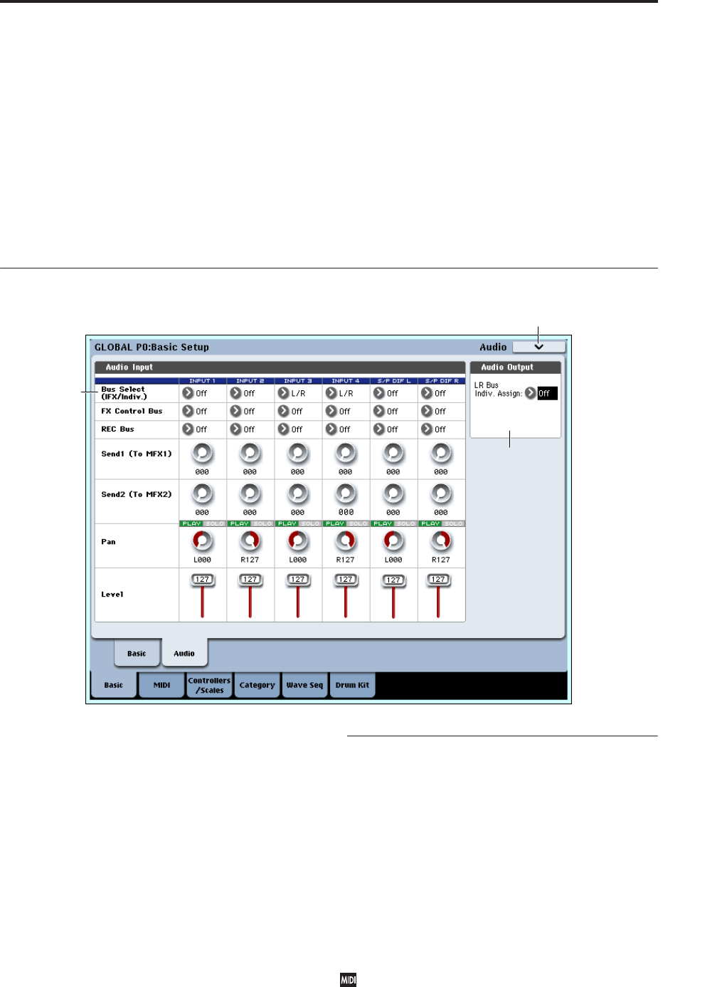
Global P0: Basic Setup 0–2: Audio Input
647
• 0: Write Global Setting. For more information, see
“Write Global Setting” on page 682.
• 1: Set Program User-Bank Type. For more
information, see “Set Program User-Bank Type” on
page 682.
• 2: Change all bank references. For more
information, see “Change all bank references” on
page 682.
• 3: Touch Panel Calibration. For more information,
see “Touch Panel Calibration” on page 682.
• 4: Half Damper Calibration. For more information,
see “Half Damper Calibration” on page 683.
• 5: Pad Calibration. For more information, see “Pad
Calibration” on page 683.
• 6: LCD Setup. For more information, see “LCD
Setup” on page 683.
• 7: Update System Software. For more information,
see “Update System Software” on page 684.
• 8: Expansion Sample Setup. For more information,
see “Expansion Sample Setup” on page 684.
• 9: Display Public ID. For more information, see
“Display Public ID” on page 684.
0–2: Audio Input
Here you can select the analog/digital audio signal
input sources, and specify their input level, bus, and
master effect sends.
The settings you make in this page are valid in the
following situations:
• When this page is open.
• In Program, Combination, and Sequencer modes, if
you’ve checked “Use Global Setting” (Program,
Combination, Sequencer 0–8a).
• In other pages of Global mode, if the mode in
which you were immediately prior to entering
Global mode was in state “2” (above).
• In Disk mode, if the mode in which you were
immediately prior to entering Disk mode was in
state “2” (above).
0–2a: Audio Input
Input1, Input2, Input3, Input4
These are the settings for inputting analog audio
sources such as mics or instruments connected to the
INPUT 1–4 jacks.
S/P DIF L, S/P DIF R
These are the settings for inputting a digital audio
source such as a DAT connected to the S/P DIF IN jack.
The S/P DIF input and output support 48 kHz and 96
kHz sample rates. Make this selection in “S/P DIF
Sample Rate” (0–1d).
When using the S/P DIF inputs, make sure that the
System Clock parameter is set appropriately. For
more information, see “System Clock” on page 644.
Bus Select (IFX/Indiv.) [L/R, IFX1…12, 1…8,
1/2…7/8, Off]
This specifies the main bus routing for the input signal.
0–2a
0–2b
0–2PMC


