


Program P3: Filter 3–1: Filter1
61
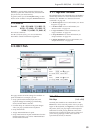
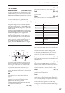
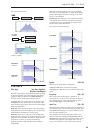
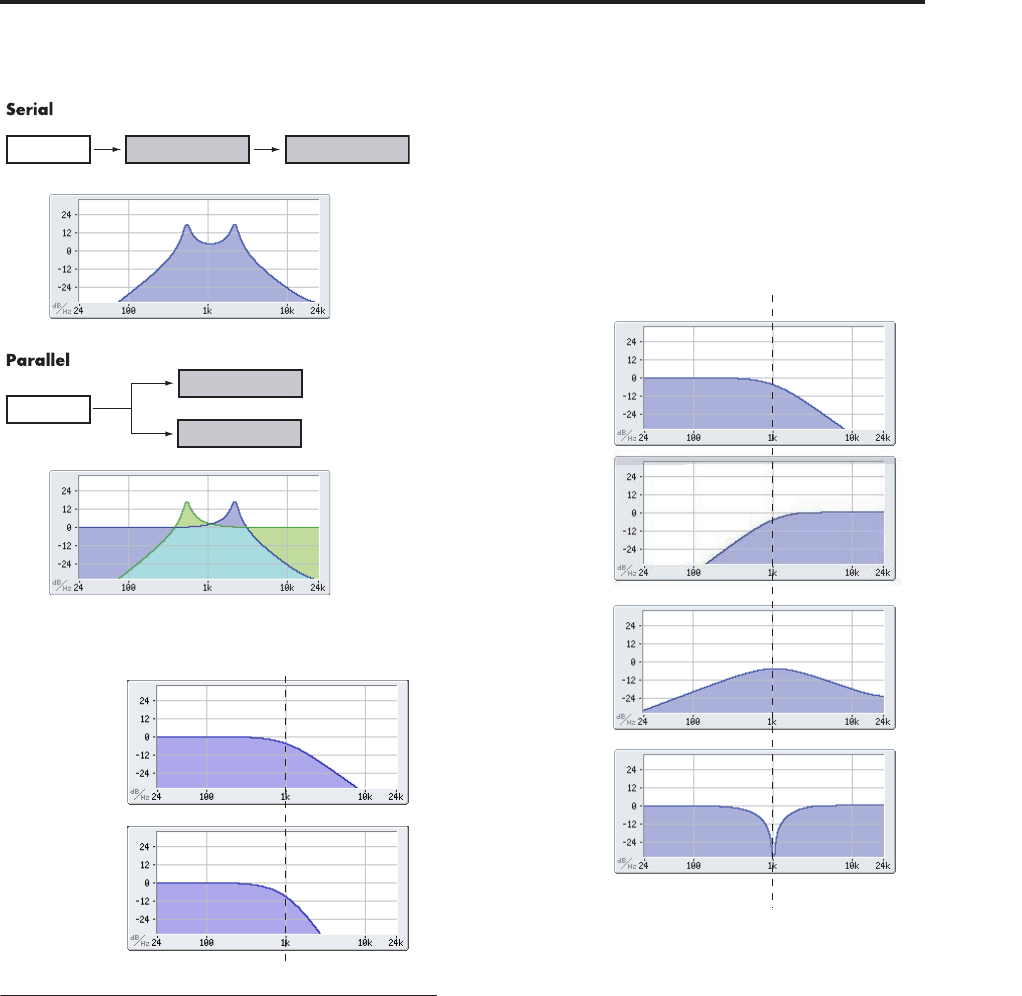
Serial and Parallel Routing
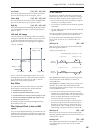
12db/oct / 24db/oct
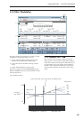
3–1b: Filter A
Filter Type [
Low Pass, High Pass,
Band Pass, Band Reject
]
The filter will produce very different results depending
on the selected filter type. The selections will change
slightly according to the selected Filter Routing, to
show the correct cutoff slope in dB per octave.
Low Pass. This cuts out the parts of the sound which
are higher than the cutoff frequency. Low Pass is the
most common type of filter, and is used to make bright
timbres sound darker.
High Pass. This cuts out the parts of the sound which
are lower than the cutoff frequency. You can use this to
make timbres sound thinner or more buzzy.
Band Pass. This cuts out all parts of the sound, both
highs and lows, except for the region around the cutoff
frequency. Since this filter cuts out both high and low
frequencies, its effect can change dramatically
depending on the cutoff setting and the oscillator’s
multisample.
With low resonance settings, you can use the Band
Pass filter to create telephone or vintage phonograph
sounds. With higher resonance settings, it can create
buzzy or nasal timbres.
Band Reject. This filter type–also called a notch filter–
cuts only the parts of the sound directly around the
cutoff frequency. Try modulating the cutoff with an
LFO to create phaser-like effects.
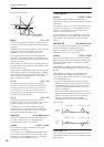
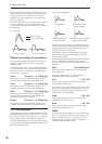
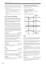
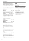
Filter Types and Cutoff Frequency
Bypass [Off, On]
This lets you bypass Filter A completely.
If Bypass is Off, Filter A functions normally.
When Bypass is On, Filter A has no effect on the input
signal.
Frequency [00…99]
This controls the cutoff frequency of Filter A, in
increments of 1/10 of an octave. The specific effect of
the cutoff frequency will change depending on the
selected Filter Type, as described above.
Input Trim [00…99]
This adjusts the volume level at the input to the filter. If
you notice that the sound is distorting, especially with
high Resonance settings, you can turn the level down
here, or at the Output Level.
Note: the filter will not clip internally, so there is no
difference between adjusting the Input Trim and the
Output Level. Either of these controls will allow you to
minimize clipping later in the signal chain, such as
may occur in the Drive section and in some effects.
Filter A (Low Pass)Oscillator Filter B (High Pass)
Oscillator
Filter A (Low Pass)
Filter B (High Pass)
Low Pass:
12dB/oct
Low Pass:
24dB/oct
Low Pass
High Pass
Band Pass
Band Reject
Cutoff Frequency