


EXi: MS-20EX
298
Note that the MG’s LED is on when it is low. Initially,
this seems like the opposite of what one might expect.
When using the MG to trigger the EGs, however, this
makes perfect sense: the EGs start when the LED goes
on, and release when the LED goes off.
EG 1 TRIG IN jack
This is similar to the TRIG IN jack, above, but it
triggers Envelope Generator 1 only.
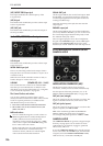
6–1f: Modulation VCA (MVCA)
This is a second VCA, intended for scaling modulation
signals.
For instance, to create a delayed vibrato:
1. Connect the MG triangle wave output to the
MVCA input
2. Connect the MVCA output to the TOTAL input
EG 1 is normalled to the CONTROL input, so without
any additional connections, you can simply:
3. Adjust the EG 1 Delay and Attack controls to
create the desired delay and fade-in times
CONTROL INPUT jack
This controls the level of the MVCA. It’s normalled to
the EG 1 output, but you can patch in any other control
signal.
IN jack
This is the input to the VCA.
OUT jack
This is the output of the VCA–the input signal scaled
by the control signal.
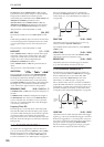
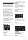
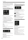
6–1g: NOISE GENERATOR
These outputs provide pink and white noise,
respectively. You can use these as sound sources or as
modulation signals.
PINK output jack
Pink noise has a darker sound than white noise, with
reduced high frequency components.
WHITE output jack
White noise is classic broad-band noise.
Note that white noise is also available as a waveform
in VCO 1.
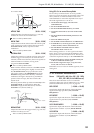
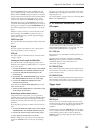
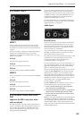
6–1h: Mod Wheel and Mod Switch
The Mod Wheel and Switch jacks allow you to select
any AMS source (controllers, EGs, LFOs, step
sequencer etc.), scale it via Intensity, and then route the
signal into the patch panel.
For more information, see “Mod Wheel and Mod
Switch” on page 301.
(Mod Wheel) jack
This lets you select, scale, and route the first AMS
signal. This could be the Mod Wheel, if you wish–but it
could also be any other AMS source.
(Mod Switch) jack
This lets you select, scale, and route the second AMS
signal. You can use any AMS source, including
continuous sources such as LFOs and EGs; the
selection is not limited to on/off switches.
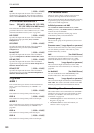
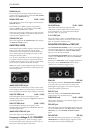
6–1i: Keyboard Trigger and CV outputs
KBD CV OUT jack
This allows you to route the keyboard’s control voltage
(which is a signal representing the current note) to
other parts of the synthesizer.
KBD TRIG OUT jack
Whenever you play a key on the keyboard, a trigger
signal is generated.
Using the Parameter Details box, you can select
whether this trigger represents Note Gate + Sustain,
or Note Gate only.
Note Gate + Sustain is the default, and is most
appropriate for general use.
Note Gate is useful for keyboard trigger operation
within self-triggering patches. For more information,
see “Tip: Creating self-triggering patches” on page 295.