


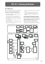
EXi: AL-1 Analog Synthesizer
178
Carrier [OSC 2, Ext Input]
Selects the carrier source for the ring modulator.
Ext Input uses the audio input selected under Sub
OSC/Audio Input, on the Mixer page. For more
information, see “4–3c: Sub OSC/Audio Input” on
page 179.
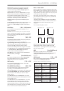
4–2c: Noise Generator
The noise generator includes Saturation, for creating
unique and chaotic noise effects, and a dedicated 1-
pole filter to control noise color.
For standard white noise, set the Saturation to 0, and
the Filter Frequency to 99.
For colored noise (such as pink noise), set the
Saturation to 0, and reduce the Filter Frequency as
desired.
To create “speckled noise” such as rocket sounds and
thunder, set Saturation to 99, and Filter Frequency to
10.
To create key contact noise (such as you might find on
vintage analog synths), create speckled noise as
described above, and then use a fast EG to control its
volume in the mixer.
Saturation [0…99]
This control clips the noise signal, for added crunch.
Subtle variations in saturation are more noticeable
with very low Filter Frequency settings (see below),
allowing you to create organic, rumbling timbres.
Filter Frequency [0…99]
This is a simple, 1-pole lowpass filter for controlling
the “color” of the noise.
▼ 4–2: Page Menu Commands
The number before each command shows its ENTER +
number-key shortcut. For more information on these
shortcuts, see “ENTER + 0-9: shortcuts for menu
commands” on page 138.
• 0: Write Program. For more information, see “Write
Program” on page 138.
• 1: Exclusive Solo. For more information, see
“Exclusive Solo” on page 138.
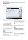
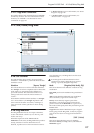
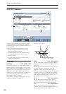
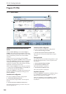
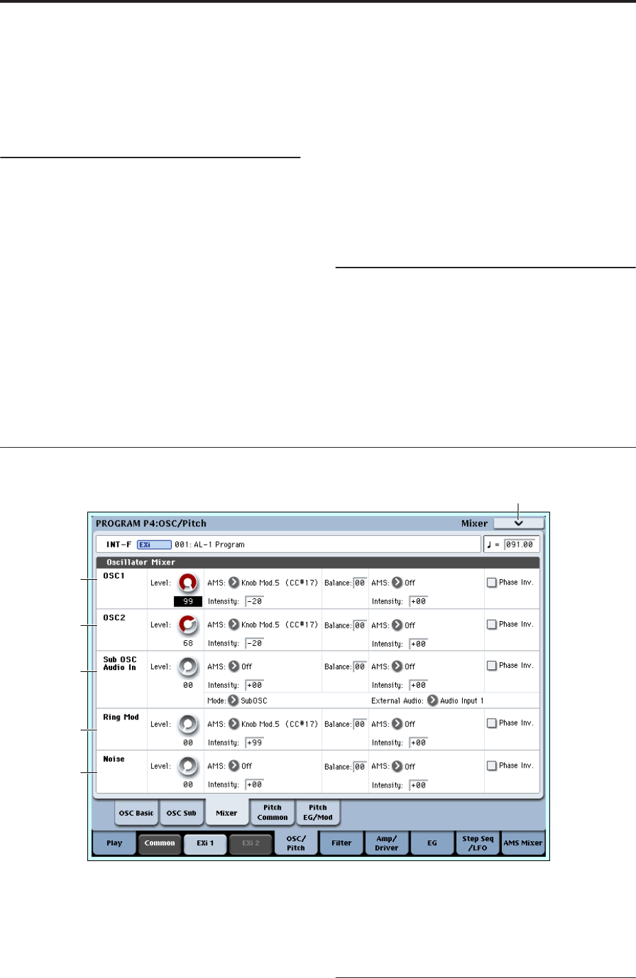
4–3: Mixer
The Mixer page controls the volume levels for the five
main parts of the Oscillator, and also controls the
routing to the filter section. For instance, you can:
• Control the volume levels for Oscillator 1,
Oscillator 2, the Sub Oscillator (or an Audio Input),
the Ring Modulator, and the Noise Generator.
• Modulate these volume levels via AMS.
• When the Filter Routing is set to either Serial or
Parallel, you can route each of the five Oscillator
elements through Filter A, Filter B, or a
combination of the two - and then modulate that
routing via AMS.
• Select an audio input to route through the filters,
driver, ring modulator, and effects.
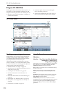
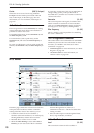
4–3a: Oscillator 1
Level [0…99]
This controls the volume level for Oscillator 1.
4–3PMC
4–3a
4–3b
4–3c
4–3d
4–3e