


EXi: MS-20EX
296
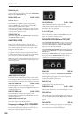
(LPF) CUTOFF FREQ input jack
This input modulates the cutoff frequency of the
Lowpass Filter.
(LPF) IN jack
This Patch Panel modification provides a direct input
to the Lowpass Filter.
(LPF) OUT jack
This Patch Panel modification provides the output of
the Lowpass Filter.
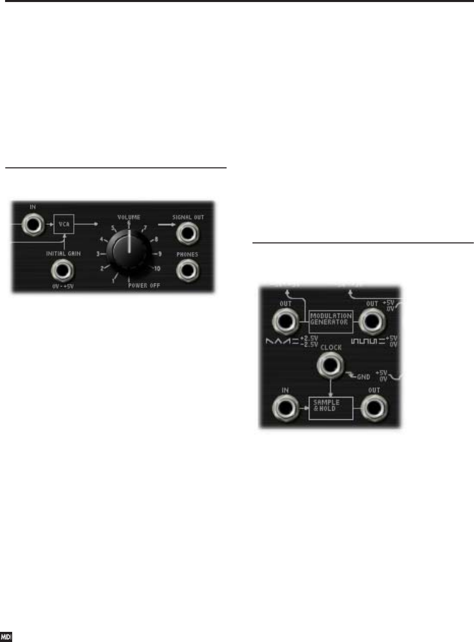
6–1c: VCA, VOLUME, and outputs
VCA IN jack
This Patch Panel modification provides a direct input
to the main VCA.
INITIAL GAIN input jack
The VCA is internally patched to the output of EG 2.
This jack allows an external controller to vary the VCA
in addition to EG 2.
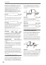
When the sum of both controllers reaches 5 volts, no
further changes in volume will occur.
VOLUME [POWER OFF, 0.01…10.00]
This controls the basic volume level of the MS-20EX.
Note that you can modulate this via AMS, for each
individual voice; for more information, see “Using EGs
3–6 to control the amplitude” on page 291.
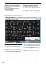
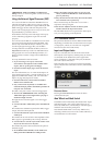
The Control Surface and volume
You can also control the volumes of EXi 1 and 2
directly from the Control Surface sliders. These volume
levels are separate parameters, in addition to the
individual EXi Amp Levels. To do so:
1. Press the Control Surface Timbre/Track button.
2. Move Slider 1 to set the volume for EXi 1, and
Slider 2 for EXi 2.
MIDI and volume
You can control the Program’s overall volume via
MIDI using both Volume (CC#7) and Expression
(CC#11). When used one at a time, the two
controllers work in exactly the same way: a MIDI
value of 127 is equal to the VOLUME setting, and
lower values reduce the volume.
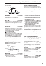
If both CC#7 and CC#11 are used simultaneously,
the one with the lower value determines the
maximum volume, and the one with the higher
value scales down from that maximum.
SIGNAL OUT jack
On the original MS-20, this was the final output. With
the MS-20EX, you may find it useful for routing the
overall output signal back into the patch–such as for
creating a feedback loop.
Note that connecting to this jack does not mute the
output signal.
PHONES output jack
On the original MS-20, this was used for headphones
(of course!). With the MS-20EX, you can use it to route
the overall output signal back into the patch, as with
the “SIGNAL OUT jack,” above.
Since its original purpose was to drive headphones,
the gain of the PHONES output is about 15dB higher
than that of the SIGNAL OUT. It also clips (with
distortion) at around -5dB below the max output level.
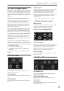
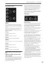
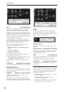
6–1d: MODULATION GENERATOR and
SAMPLE & HOLD
MODULATION GENERATOR (MG)
The MG has separate outputs for its two basic
waveforms, so that you can use both simultaneously.
For descriptions of the MG parameters, see “5–1b:
MODULATION GENERATOR (MG)” on page 289.
OUT jack (saw/triangle)
This is the output for the saw/triangle waveform. The
signal is centered around zero, from –5.00 to +5.00.
OUT jack (pulse/square)
This is the output for the pulse/square waveform. The
signal is unipolar, from 0.00 to 10.00.
Note: when used through AMS and EXTERNAL
MODULATION, the signal ranges for both the
saw/triangle and pulse/square are –10.00 to +10.00.
SAMPLE & HOLD
The SAMPLE & HOLD can generate a stepped output
from any varying input. You can use this to create
random filter or pitch effects, arpeggios, quantized
LFOs or EGs, and so on.
To use the SAMPLE & HOLD, there must be a trigger
source connected to the CLOCK input, and some sort
of signal (such as the NOISE GENERATOR, VCOs,
AMS sources etc.) connected to the IN jack.