


Program P0: Play 0–8: Audio Input/Sampling
13
Tip: You can use the control surface to control this
parameter. For more information, see “Using the
control surface to adjust Audio Input” on page 11.
Level [000…127]
This controls the level of the external audio signal. The
default is 127.
The analog audio signals from AUDIO INPUTS 1–4 are
converted into digital form by an A/D converter. This
parameter sets the level of the signal immediately after
this conversion.
If the sound is distorted even though this level setting
is very low, see “Tips for eliminating distortion when
using the analog inputs,” below.
Tip: You can use the control surface to control this
parameter. (See “Using the control surface to adjust
Audio Input” on page 11.)
Avoiding extraneous noise
If audio cables are connected to AUDIO INPUTS 1–
4, any noise carried by the cables will enter into the
OASYS mixer structure. Similarly, the S/P DIF
input may carry noise from external devices. This
may include hiss, hum, and other audio noise.
To avoid noise from unused audio inputs, either:
• Set the input’s Level to 0
or
• Set all of the bus assignments to Off, including Bus
Select (IFX/Indiv. Out Assign), REC Bus, and FX
Control Bus
If no audio cables are connected to AUDIO INPUTS
1–4, the input signals are forced to zero, preventing
any additional noise.
ADC OVERLOAD!
If the signal level from AUDIO INPUT 1–4 jacks is too
high, the “ADC OVERLOAD!” indication will appear.
You’ll need to adjust the MIC/LINE gain select
switches and/or LEVEL knobs (for AUDIO INPUTS 1
and 2 only), or the output level of your external audio
source.
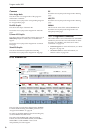
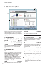
0–8b: Recording Level [dB]
Recording Level [–Inf, –72.0…+0.0…+18.0]
This adjusts the signal level at the final stage of
sampling.
The Recording Level setting is made for Program
mode as a whole, and is not saved independently with
each Program.
Level Meter
This shows the signal level at the final stage of
sampling, after any adjustments on the Audio Inputs
page, any effects, etc. The meter is active only during
standby mode and recording.
CLIP!
If 0 dB is exceeded, the display will indicate “CLIP!”
This means that the level of the sampling signal is too
high; in this case, adjust the Recording Level, and if
necessary follow the instructions under “Tips for
eliminating distortion when using the analog inputs,”
below.
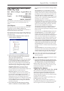
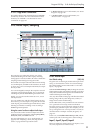
Setting levels
For the best results, set the levels as described below:
1. Press the SAMPLING REC switch.
OASYS will enter sampling standby mode, and the
Level Meter becomes active.
2. Initially, set the Recording Level to 0.0dB.
3. Adjust the level of the input signal so that it is as
high as possible without activating the CLIP! or
ADC OVERLOAD! messages.
If you’re using AUDIO INPUTS 1 and/or 2, adjust the
volume using rear-panel MIC/LINE switches and
LEVEL knobs.
If you’re using AUDIO INPUT 3 and/or 4, or the
S/P DIF input, adjust the output level of your external
audio source.
If you’re sampling external audio through the internal
effects, you may also need to adjust the individual
effects input and/or output level parameters.
If you’re using internal sounds, adjust the levels using
the control surface, effects input/output trim, etc.
4. If the level is still not high enough, increase the
Recording Level using the on-screen slider.
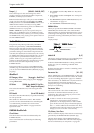
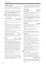
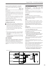
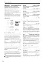
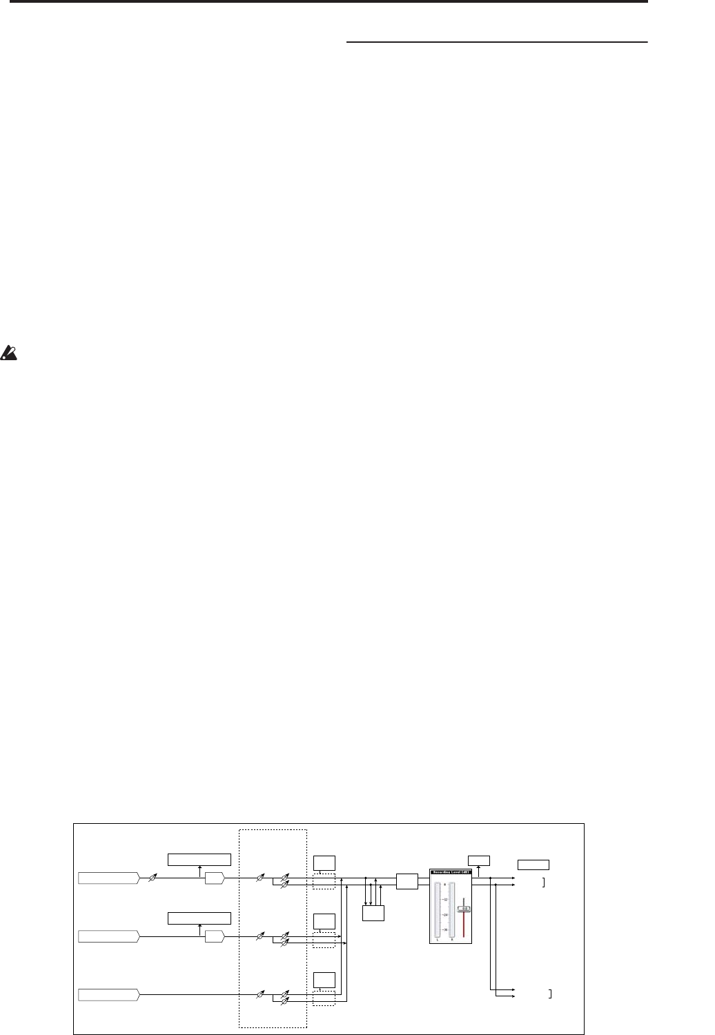
AUDIO INPUT 1, 2
ADC
Analog to
Digital
Converter
LEVEL
(MIC/LINE)
(MIN...MAX)
ADC OVERLOAD !!
L-Mono
R-Mono
Stereo
REC Sample Setup
"Mode" (0–8c)
"Level"
[127=0dB]
"Pan"
Insert
Effects
CLIP !!
"Recording Level" (0–8b)
[–inf ... 0.0dB ... +18.0dB]
"Audio Input" (0–8a)
L/MONO
"Source Bus" (0-8c)
= L/R
R
AUDIO
OUTPUT
Bus(IFX/Indiv.)
= L/R or IFX1-12
Total
Effects
Master
Effects
AUDIO INPUT 3, 4
ADC
Analog to
Digital
Converter
ADC OVERLOAD !!
"Level"
[127=0dB]
"Pan"
Insert
Effects
S/P DIF IN (L, R)
"Level"
[127=0dB]
"Pan"
Insert
Effects
Sampling
Audio input/output