


Program P5: Filter 5-1: Filter Basic
261
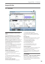
Program P5: Filter
5-1: Filter Basic
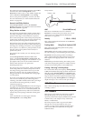
Interaction between the filters and the
mixer
When the Filter Routing is set to either Single or
24dB/oct, the routing from the String section into the
Filter section is fairly simple. There’s only a single
filter, and that filter processes the entire sound.
Things can get more interesting when the Filter
Routing is set to Serial or Parallel. In these modes, The
Mixer page’s Balance parameters let you separately
control the filter routing for each of the five inputs: the
String, the PCM Oscillator, the Noise Generator,
Pickup1, and Pickup2.
When an input’s Balance is set to 0, it goes into Filter
A. (Note that if the Filter Routing is set to Serial, the
signal will also pass through Filter B.)
If the input’s Balance is set to 99, it goes directly into
Filter B, regardless of whether the routing is set to
Serial or Parallel.
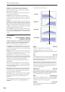
Standard serial configuration
To create a standard serial filter configuration:
1. Set the Filter Routing to Serial.
This connects the output of Filter A to the input of
Filter B.
2. Set all of the mixer’s Balance controls to 0.
This makes all of the inputs go to Filter A first, and
then through Filter B.
Standard parallel configuration
To create a standard parallel filter configuration:
1. Set the Filter Routing to Parallel.
2. Set all of the mixer’s Balance controls to 50.
This routes all of the inputs to both filters, at equal
volumes.
Dual signal paths
You can also send the String through Filter A, and the
PCM Oscillator through Filter B (or vice-versa), to
create a layered sound. For instance:
1. Set the Filter Routing to Parallel.
2. Set the String’s Balance to 0.
This routes the String to Filter A.
3. Set the PCM Oscillator’s Balance to 99.
This routes the PCM Oscillator to Filter B.
Anywhere in-between
If an input’s Balance is set between 1 and 98, it will go
to a combination of both filters–so that many “in
between” filter effects are available.
Finally, by modulating an input’s Balance via AMS,
you can crossfade between routing through Filter A
and Filter B.
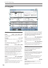
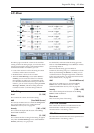
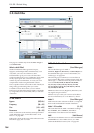
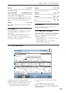
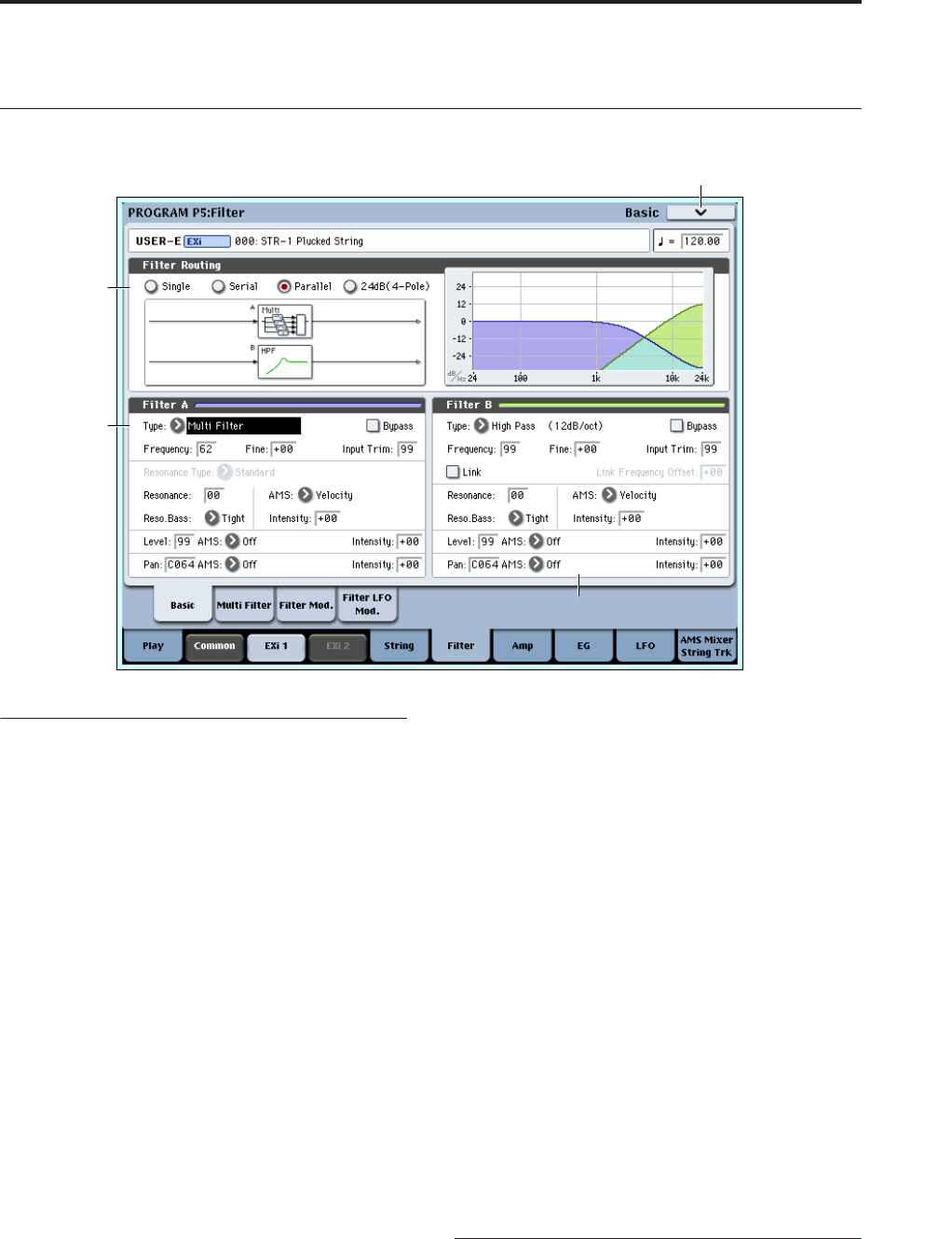
5-1a: Routing
Filter Routing [Single, Serial, Parallel, 24dB/oct]
There are two filters, Filter A and Filter B. This
parameter controls whether one or both of the filters
are used, and if both are used, it controls how they are
connected to each other.
5–1PMC
5–1c
5–1a
5–1b