


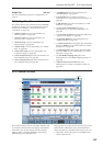
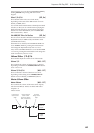
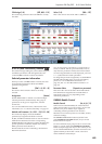
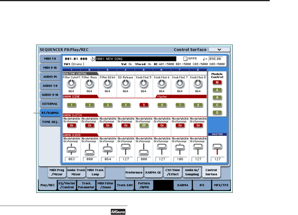
Sequencer P0: Play/REC 0–9: Control Surface
445
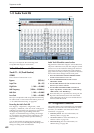
CC# Assign (1–8) [Off, 000…119]
This read-only parameter shows the MIDI CC sent by
the slider.
Value (1–8) [000…127]
This is the current value of the slider’s MIDI CC.
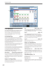
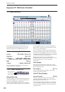
0–9f: RT (Real Time Knobs)/KARMA
This Control Assign setting lets you modulate Program
and Effects parameters with the eight knobs, and
control KARMA with the switches and sliders.
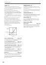
Selected parameter information
When you select a KARMA Slider or Switch, this area
shows detailed information about its KARMA
parameter assignments.
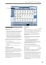
Control [(SW1…8, SL1…8)]
This shows which Switch or Slider is currently
selected.
Assignment [Name]
Each KARMA Slider or Switch can control multiple
internal parameters simultaneously. The group of
parameters can be given a single name, which is
shown here.
You can select different names, if desired. For more
information, see “7–9: Name/Note Map” on page 121
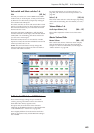
Module and Parameter [A…D 01…32, P 01…08]
This read-only display shows the KARMA
parameter(s) assigned to the Slider or Switch.
A, B, C, and D mean that the slider or switch controls a
GE Real-Time Parameter from the corresponding
KARMA Module. The following number identifies the
specific parameter within the module. For instance,
A22 is parameter 22 of Module A.
P means that the switch is controlling a Performance
Real-Time Parameter.
You can assign many parameters to a single slider or
switch, if desired. Due to space limitations, however,
only first four parameters will be shown here. If there
are more assignments than can be displayed, you’ll see
a “>” symbol after the fourth parameter.
To change the parameter assignments, use the KARMA
GE RTP and Perf RTP pages. For more information,
please see “7–5: GE Real-Time Parameters” on
page 110, and “7–6: Perf Real-Time Parameters” on
page 112.
Parameter Value [Depends on parameter]
This shows the value of the GE or Performance Real-
Time Parameters assigned to the selected Slider or
Switch. The range can vary, depending on the
individual parameters.
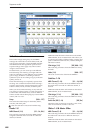
KARMA Module Control
Module Control [M, A, B, C, D]
When used to control KARMA, the Control Surface
sliders and switches are five layers deep: one for each
Module (A-D), and a Master Layer capable of
controlling selected parameters from all of the
Modules at once. Each layer has its own Slider, Switch,
and Scene settings.
The Module Control radio buttons (and the front-
panel MODULE CONTROL button) let you switch
between these five layers.
To select a different layer, just press its on-screen radio
button, or use the front-panel MODULE CONTROL
button to step through each layer in turn. When you do
so, all of the KARMA Sliders, Switches and Scenes will
update instantly to show their current values and
names within the selected layer.
0–9f