


Program P6: Patch Panel 6-1: Patch Panel
295
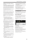
Tip: Creating self-triggering patches
Normally, new notes and EGs 1 and 2 are triggered by
playing notes on the keyboard. They don’t have to be,
however. You can use the MG Square/Pulse output,
the Trig Out of the External Signal Processor, or AMS
signals from the Wheel or Switch jacks to trigger one or
both EGs.
Note: EGs 1 and 2 trigger when the input is at 0
(“low”), such as when the MG Square/Pulse is in the
bottom portion of the waveform. The MG’s indicator
LED is on during this portion of the waveform.
You can also use AMS (such as LFOs) to reset EGs 3-6,
if desired. Finally, the Common Step Sequencer and
LFO can also be reset via a selection of controllers,
including the Vector EG CCs.
Even when a patch is self-triggering, it will only play
when a note is played on the keyboard, held by the
damper pedal, or held via the Program Basic page’s
Hold parameter. When the note is released (by lifting
up on the keyboard or damper pedal, or turning off
Hold), the EG selected by the VOICE ALLOCATION
parameter will automatically enter its release phase,
and will no longer re-trigger. All other EGs will
continue to re-trigger, according to the Patch Panel and
AMS settings.
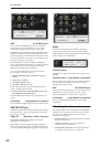
In some cases, you may want some elements of the
patch to re-trigger automatically, while others are still
triggered from the keyboard. To allow the keyboard to
act as a trigger while you are holding the sustain pedal
(or while Hold is enabled):
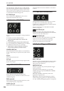
1. Select the KBD TRIG OUT jack.
2. In the Parameter Details box, set Trigger On to
Note Gate.
For more information, see “KBD TRIG OUT jack” on
page 302.
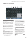
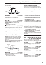
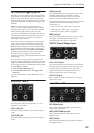
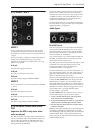
6–1a: VCOs 1 and 2
For descriptions of the VCO parameters, see “4-1a:
Oscillators” on page 285.
(VCO 1) OUT jack
This Patch Panel modification provides the output of
VCO 1.
(VCO 2) OUT jack
This Patch Panel modification provides the output of
VCO 2.
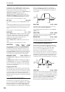
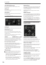
TOTAL input jack
This input modulates the frequencies of VCOs 1 and 2,
the HPF, and the LPF. It’s normalled to the MG
sawtooth/triangle output, but you can use patch
cables to connect any other modulation source.
Each of the destinations has a knob to scale the amount
of modulation from the TOTAL input. For more
information, see:
• VCO 1 and 2 pitch: “MG/T.EXT” on page 286
• HPF frequency: “MG/T.EXT” on page 287
• LPF frequency:“MG/T.EXT” on page 287
FREQ input jack
This input modulates the frequencies of VCOs 1 and 2.
The signal is scaled by the EG1/EXT knob, as
described under “EG1/EXT” on page 286.
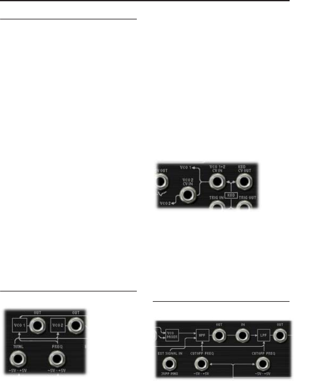
VCO CV (Control Voltage) inputs
VCO 1+2 CV IN jack
This controls the basic pitch of both VCO1 and VCO2.
Normally, this signal comes from the notes played on
the keyboard (or via MIDI). You can patch other
signals into this jack to create special effects, or to
follow the pitch of an external audio input.
VCO 2 CV IN jack
This is similar to “VCO 1+2 CV IN jack,” above, but
affects VCO 2 only.
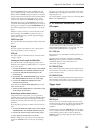
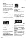
6–1b: HPF and LPF
EXT SIGNAL IN jack
This is a direct input to the HPF, summed with the
output of the VCO Mixer.
(HPF) CUTOFF FREQ input jack
This input modulates the cutoff frequency of the
Highpass Filter.
(HPF) OUT jack
This Patch Panel modification provides the output of
the Highpass Filter.