


893
KARMA GE guide
About the KARMA GE guide
This section of the manual explains the GE parameters
of the KARMA function built into the OASYS,
organized according to the groups that make up the
Generated Effects.
The OASYS provides more than two thousand preset
GEs (Generated Effects). For each GE, up to thirty-two
of the more than four hundred internal GE parameters
have been selected for optimal control from the
OASYS.
The GE parameters and ranges that can be controlled
will differ for each GE.
Some GE parameters are related to other parameters,
and are affected by them. In this case, the parameters
that are producing the effect may not always be
displayed, since they may already be preset for that
GE.
Furthermore, the KARMA-related parameters in pages
7–0 – 7–9 of each mode may also function differently,
or not at all, depending on the settings of these GE
parameters.
Some of the internal parameters of each GE are
displayed in the Voice Name List. (
☞VNL)
In order to explain the GEs, some of the examples in
this document mention these internal parameters, even
though they cannot be viewed or changed on the
OASYS.
Illustrations in the GE guide
Some of the illustrations in this document include
displays of data, such as pattern grids, which are not
shown on the OASYS LCD screen.
How to read the “GE Guide”
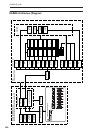
The GEs (Generated Effects) are organized into fifteen
groups. Each group has GE parameters. For more
information, see “KARMA Architecture (Diagram)” on
page 896.
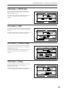
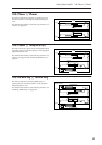
The 7–5: GE Real-Time Parameters page shows the
group name, parameter name, and parameter value of
the GE parameters.
You can use the 7–5: GE Real-Time Parameters page to
check the group name and parameter name of the GE
parameter you wish to look up, and then find it in the
GE Guide.
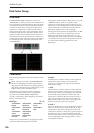
Here’s an example from Program mode.
Access the Program 7–5: GE Real-Time parameters
page, and display the GE parameters in the LCD
screen. For more information, see “7–5: GE Real-Time
Parameters” on page 110.
The GE parameters displayed in the LCD screen show
the group name and parameter name.
For example in the case of 01. Rhythm: Swing %, the
group is Rhythm Group and the parameter is “Swing
%.”
The explanation for “Swing %” is given on p.13
“Rhythm Group ”Swing %.”
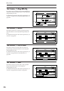
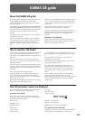
The parameter value is displayed by “Value” at the
right of the parameter name.
The “Real-Time Control Range” (minimum and
maximum values that the parameter can be varied
between by real-time control or direct editing) is
displayed by “Min” and “Max” next to the “Value”
field.
When loading a GE, the default value and editing
range of the parameter is preset for each GE.
Depending on the selected GE, the same GE parameter
may have a different default value and a different
editing range.
How GE parameter names are displayed
For some GE parameters, the following information is
shown in addition to the parameter name.
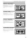
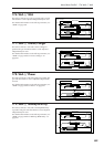
Parameter name [Phase]
This is shown for most GE parameters within the
following groups (some that are not related to phases
will not show this information):
Phase Group
Rhythm Group
Duration Group
Index Group
Cluster Group
Velocity Group
CCs Group
WaveSeq Group
Display example
[1]: Phase 1 is controlled
[2]: Phase 2 is controlled
[B]: Both phases 1 and 2 are controlled
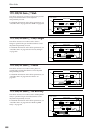
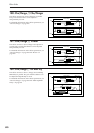
CCs: parameter name #No. #No.
Parameters of the CCs Group also indicate the MIDI
message that are controlled by CC-A and CC-B.
[Phase]