


Program mode: HD-1
60
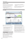
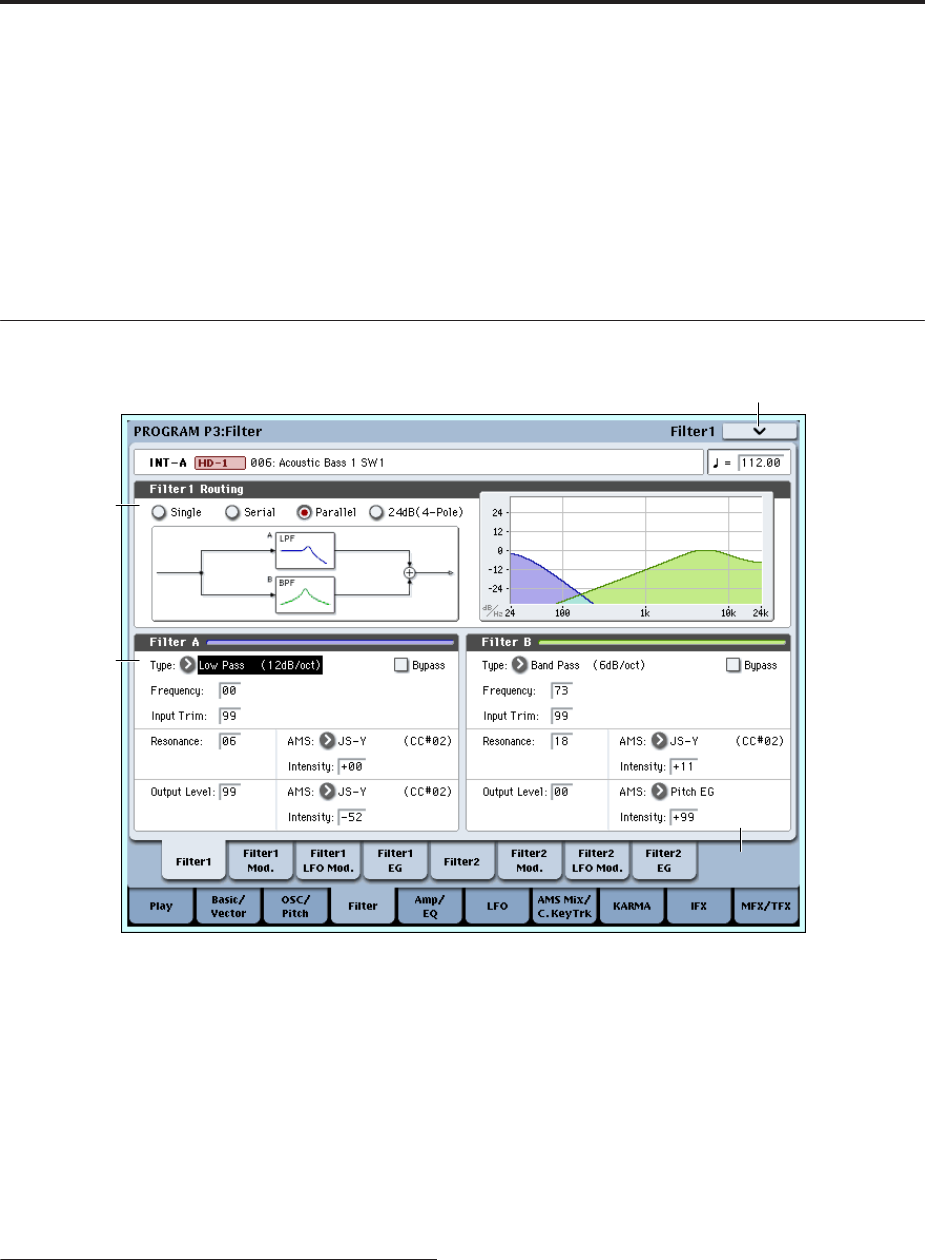
Program P3: Filter
Filtering can make subtle or dramatic changes to the
oscillator’s timbre. Each oscillator has two multimode
resonant filters, A and B, as well as a dedicated filter
envelope and keyboard tracking generator.
These pages let you control all aspects of the filters.
Among other things, you can:
• Make basic settings for each oscillator’s filters,
including routing, modes, cutoff, resonance, etc.
• Set up filter modulation, including keyboard
tracking, the filter envelope, LFO modulation, and
AMS control.
Note that when the Oscillator Mode is set to Single,
only Oscillator 1’s filters are active; the pages for
Oscillator 2’s filters will be grayed out.
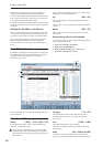
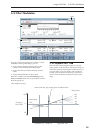
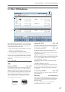
3–1: Filter1
This page contains all of the basic settings for
Oscillator 1’s Filter A and Filter B. For example, you
can:
• Set up the filters to produce a single 12dB/oct filter,
dual 12dB/oct filters in either serial or parallel
routing, or a single 24dB/oct filter.
• Set each of the two filters to Low Pass, High Pass,
Band Pass, or Band Reject modes.
• Set the cutoff, resonance, and input and output
levels of each filter, including modulation of
resonance and output level.
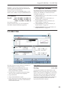
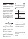
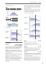
3–1a: Filter Routing
Filter Routing [Single, Serial, Parallel, 24dB/oct]
Each oscillator has two filters, Filter A and Filter B.
This parameter controls whether one or both of the
filters are used, and if both are used, it controls how
they are connected to each other.
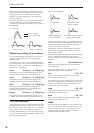
Single. This uses only Filter A as a single 2-pole,
12dB/octave filter (6dB for Band Pass and Band
Reject). When this option is selected, the controls for
Filter B will be grayed out.
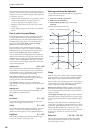
Serial. This uses both Filter A and Filter B. The
oscillator first goes through Filter A, and then the
output of Filter A is processed through Filter B.
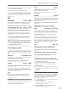
Parallel. This also uses both Filter A and Filter B. The
oscillator feeds both filters directly, and the outputs of
the two filters are then summed together.
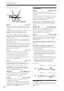
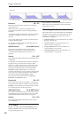
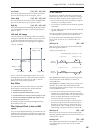
24dB/oct. This merges both filters to create a single 4-
pole, 24dB/octave filter (12dB for Band Pass and Band
Reject). In comparison to Single, this option produces a
sharper roll-off beyond the cutoff frequency, as well as
a slightly more delicate resonance. Many classic analog
synths used this general type of filter.
When 24dB/oct is selected, only the controls for Filter
A are active; the controls for Filter B will be grayed out.
3–1PMC
3–1c
3–1a
3–1b