Program mode: HD-1
70
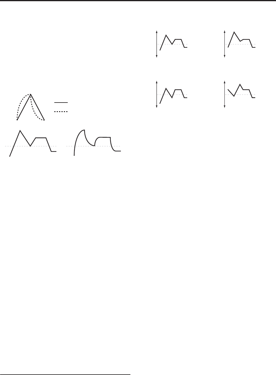
In other words, each segment’s level will change
quickly at first, and then slow down as it approaches
the next point. This tends to sound better than straight,
linear segments.
Classic analog synth envelopes made these curved
shapes naturally. The OASYS goes a step further than
vintage synths, however, and lets you control the
amount of curvature separately for each of the four
envelope segments.
Filter EG Curve
When you change the curvature, the EG times remain
the same. However, greater curvature will tend to
sound faster, because the value changes more quickly at
the beginning.
Different curve settings for up and down
You may find that different amounts of curvature are
suitable for segments which go up and segments
which go down.
For instance, a curve of 3 is a good default setting for
upward segments, such as Attack. On the other hand, a
curve of 6 or more is good for downward segments,
such as Decay and Release.
Attack [0 (Linear), 1…9, 10 (Exp/Log)]
This sets the curvature of the Attack segment - the
transition from the Start level to the Attack level.
Decay [0 (Linear), 1…9, 10 (Exp/Log)]
This sets the curvature of the Decay segment - the
transition from the Attack level to the Break level.
Slope [0 (Linear), 1…9, 10 (Exp/Log)]
This sets the curvature of the Slope segment - the
transition from the Break level to the Sustain level.
Release [0 (Linear), 1…9, 10 (Exp/Log)]
This sets the curvature of the Release segment - the
transition from the Sustain level to the Release level.
3–4c: Level Modulation
These settings let you use any AMS source to control
the Level parameters of the EG. The Start, Attack, and
Break levels share a single AMS source, but can each
have different modulation intensities.
By using different settings for each of the three levels,
you can cause both subtle and dramatic changes to the
EG shape, as shown below.
Filter EG Level Modulation
Once an EG segment begins, it can’t be modulated
Once the EG has started a segment between two
points, that segment can no longer be modulated. This
includes both the time of the segment, and the level
reached at the end of the segment.
For instance, if the EG is in the middle of the Decay
time, you can no longer modulate either the Decay
time or the Break level.
As another example, let’s say that you’ve assigned the
Common LFO to modulate Break Level. The LFO may
be moving all the time, but the Break Level is only
affected by the LFO’s value at the instant that the
Decay segment starts. After that, the level is fixed.
Finally, this also means that modulating the Start level,
Attack level, or Attack time will not affect notes that
are already sounding, unless the EG is then reset via
AMS.
AMS [List of AMS Sources]
Selects an AMS source to control the EG’s Level
parameters.
For a list of AMS sources, see “AMS (Alternate
Modulation Source) List” on page 967.
Start [–99…+99]
This controls the depth and direction of the AMS
modulation for the Start level.
For example, if you set the AMS source to Velocity and
set Start to +99, the Start level will increase as you play
harder. If you instead set Start to –99, the Start level
will decrease as you play harder.
Attack [–99…+99]
This controls the depth and direction of the AMS
modulation for the Attack level.
Break [–99…+99]
This controls the depth and direction of the AMS
modulation for the Break level.
Curve = 0 (Linear)
Curve = 0 (Linear)
Curve = 10 (Exp/Log)
Curve = 10 (Exp/Log)
Original Shape
Positive AMS on Start and Break,
Negative AMS on Attack
Negative AMS on Start,
Attack, and Break
Positive AMS on Start,
Attack, and Break


